
Free-form progressive multifocal refractive lens for cataract and refractive surgery

a free-form, progressive technology, applied in the field of free-form progressive multifocal refractive lens for cataract and refractive surgery, can solve the problems of many doctors and patients having poor experience, unable to accommodate the crystalline lens in the human eye to allow focusing on objects, and have gone out of favor, so as to improve distance and near focus, improve the visual acuity of patients

Inactive Publication Date: 2014-05-15
STAAR SURGICAL COMPANY INC
View PDF1 Cites 44 Cited by
  • Summary
  • Abstract
  • Description
  • Claims
  • Application Information

AI Technical Summary

Benefits of technology

This patent describes a new method for creating lenses that can improve a patient's vision by providing better focus at both far and near distances. The lenses have a special design that helps them fit snugly in the eye. This design can be created using a special lathe that can cut the lens from a blank. The technical effect is to provide a better, more complete range of vision for patients with optical issues.

Problems solved by technology

After the onset of presbyopia the crystalline lens in the human eye can no longer accommodate to allow focusing on objects at a distance and nearby objects such as books or computer screens.
Although the FDA approved one of these lenses (Crystallens), many doctors and patients had poor experience with it and it has gone out of favor.
As an added bonus, MFD lenses are designed to restore a certain level of near vision, but this is not true accommodation.
Such lenses do not accommodate, rather, they are designed to provide best focus for distance vision at the center of the lens and some degree of near vision at the periphery of the lens.
The design is simple and has some advantages and major disadvantages, such as dependence on the aperture size to have the intermediate and near vision effect.
Although the prior art designs theoretically can be implemented on a negative ICL lens, in practice, such implementation would be extremely difficult.
Therefore it would be virtually impossible to cut the rings without punching through the back surface or without seriously compromising the mechanical properties of the resulting lens.
Because of the physiological constraints of the eye, the thickness of the negative lens cannot be increased, as it would no longer fit into the very tight volume where such a lens is typically is implanted in the eye.
A second problem with the diffractive rings of the multi-period design is that if they are made on the front surface of the lens they will contact the iris.
There is a serious danger of chafing the iris as it scrapes against the rings as the iris opens and closes in reaction to the amount of light incident on the eye.
Such chafing may result in iris pigment particles being dislodged, potentially causing serious problems of inflammation and clogging of the exit channels for the aqueous humor.
On the other hand, if the rings are implanted on the back surface and they accidentally touch the crystalline lens, the insult to the crystalline lens may result in formation of a cataract within the crystalline lens.
Thirdly, diffractive surfaces are traditionally used as diffraction gratings to split light into its spectrum of colors, producing chromatic dispersion.
In the case of a diffractive multifocal IOL, the chromatic dispersion becomes a serious problem and the patients have to live with this effect and somehow learn to ignore it.
Regarding the double curvature design, it is complex to manufacture and patients report observing coma effects with this lens.
Such a lens also exhibits many of the problems discussed above, such as the difficulty of implementing two radii of curvature on a negative lens that is already extremely thin.
Another serious problem with the double curvature design is the occurrence of glare and haloes.
These problems come from the sharp transition and abrupt change in lens power where the two surfaces meet.

Method used


Image

  • Free-form progressive multifocal refractive lens for cataract and refractive surgery
  • Free-form progressive multifocal refractive lens for cataract and refractive surgery
  • Free-form progressive multifocal refractive lens for cataract and refractive surgery

Examples


Embodiment Construction

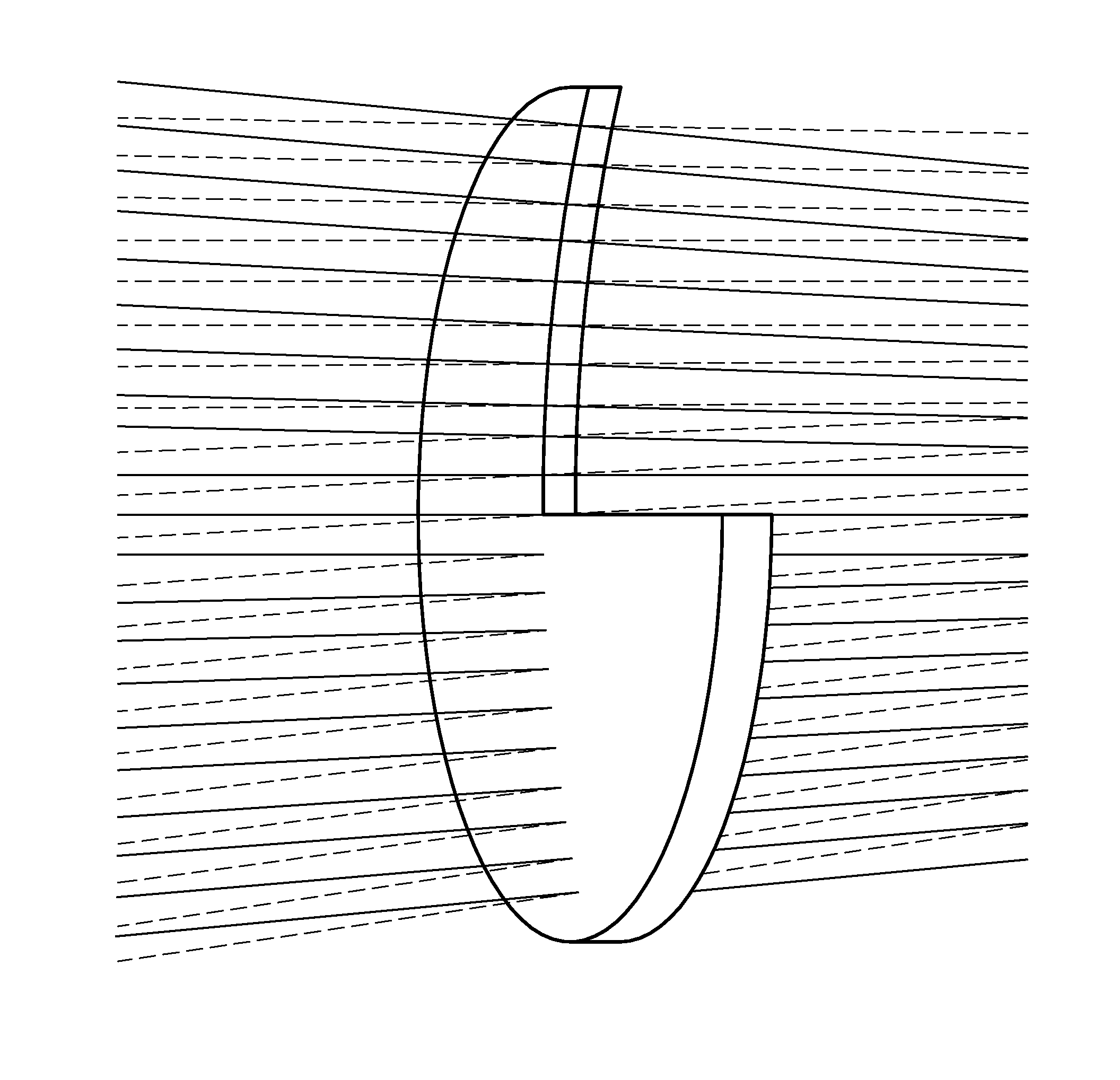
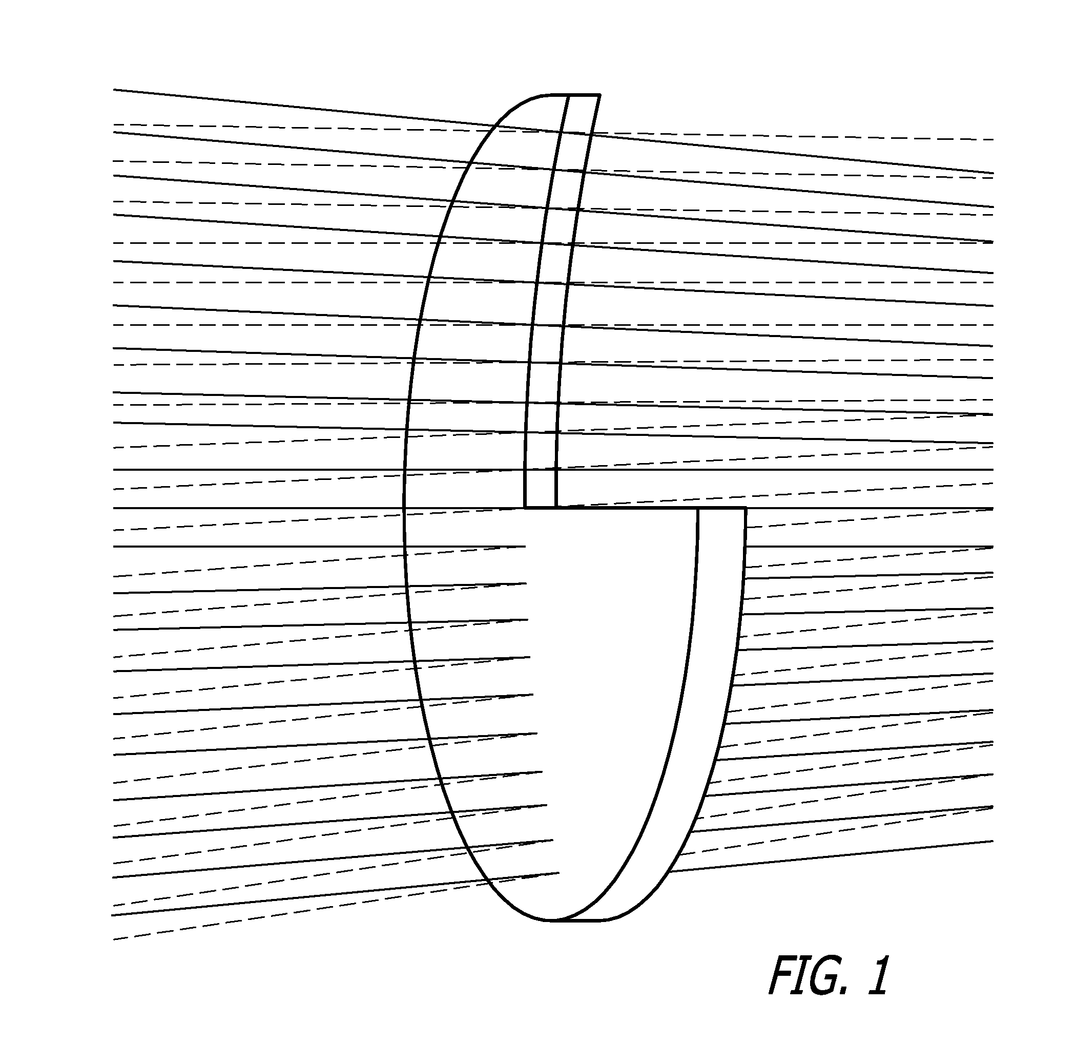
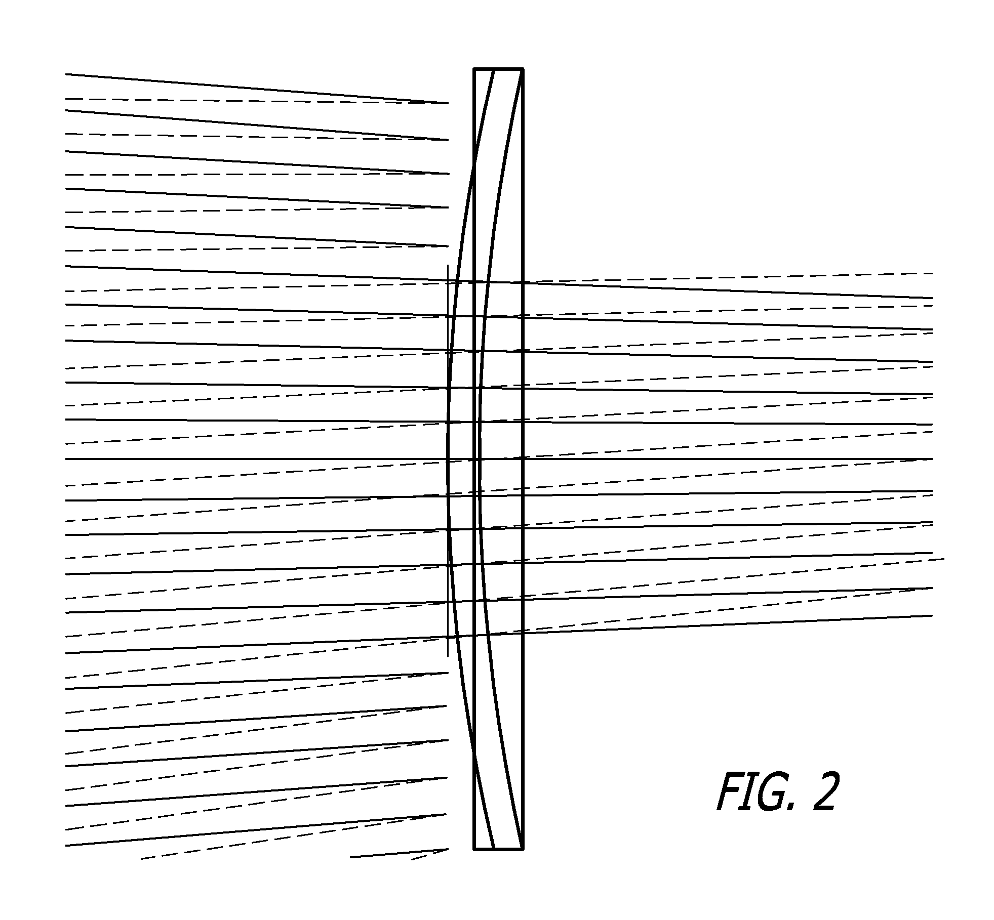
[0050]The free form progressive multi-focal refractive lens in this invention is a type of intra-ocular lens that can be used in cataract and refractive surgery. Its unique features make it a good choice to provide both distance and near vision for two age groups. Cataract patients tend to be older (60+ year olds), while refractive surgery is more common in younger patients, in their 30s and 40s.

[0051]In one embodiment, the invention is a refractive-only lens, with a free form or progressive surface. This lens design is a more complex surface than the simple spherical or conic surfaces of prior art refractive type multifocal lenses, whose optical properties can be described by a single number such as radius of curvature only in the case of a spherical lens, or by two numbers, such as a radius and a conic constant for an aspheric lens surface.

[0052]In an embodiment of the present invention, the free form multifocal lens has a base conic surface, over which is laid s surface described...


PUM


Abstract

A new type of multi-focal lens that has a free-form progressive multifocal front surface consisting of a 16th order polynomial superimposed on a standard conic base surface is described. The center region of the lens is optimized for distance vision, while simultaneously optimizing the rest of the lens for near vision. The resulting free-form even asphere polynomial surface is smooth, unlike present day diffractive multifocal designs. Additionally, this lens design is suitable for both refractive and cataract surgeries.

Description

CROSS-REFERENCES TO RELATED APPLICATIONS[0001]This application claims priority from U.S. Application No. 61 / 724,842, filed Nov. 9, 2012, incorporated by reference in its entirety.BACKGROUND[0002]After the onset of presbyopia the crystalline lens in the human eye can no longer accommodate to allow focusing on objects at a distance and nearby objects such as books or computer screens. The simplest solution to this problem consists of wearing spectacles for distance vision and reading glasses for near vision. The next step in sophistication to solve this problem is the use of bifocal lenses in spectacles so that the patient can look straight ahead through a lens for distance vision or “look down” through a lens of different power (but part of the same piece of glass on the frame) for near vision.[0003]Two other solutions have been implemented that are more sophisticated. First there are so called pseudo-accommodation lenses that are implanted in the eye and are supposed to mimic the ef...

Claims


Application Information

Patent Timeline
Patent Type & Authority Applications(United States)
IPC IPC(8): G02C7/06A61F2/16
CPCA61F2/1637G02C7/061A61F2/1618A61F2240/002
Inventor GONTIJO, IVAIRPAUL, THOMAS R.OSSIPOV, ALEXEI
Owner STAAR SURGICAL COMPANY INC
Learn More