Method And System For Transport Container Refrigeration Control

a technology for transport containers and refrigeration, applied in the field of refrigeration, can solve the problems of premature failure of compressors, damage to compressors, and non-optimal defrost-times,

Active Publication Date: 2014-05-22
CARRIER CORP
View PDF5 Cites 29 Cited by
  • Summary
  • Abstract
  • Description
  • Claims
  • Application Information

AI Technical Summary

Benefits of technology

[0003]According to an example embodiment of the present invention, a method of refrigeration control through a refrigeration system of a refrigerated transport container includes performing a defrost cycle on the refrigeration system by activating a heat source; and restarting the refrigeration system after the defrost cycle has completed, wherein restarting the refrigeration system includes performing a liquid slugging avoidance process including: initiating a compressor of the refrigeration system at a speed; opening a pressure equalization valve in parallel with the compressor in response to the initiating; opening a liquid valve in series between a condenser and an evaporator after opening of the pressure equalization valve; and closing the pressure equalization valve after a period of time.
[0004]According to another example embodiment of the present invention is a refrigeration system, comprising: a condenser; a compressor in serial communication with the condenser; an evaporator in serial communication with the condenser and the compressor; a heat source for thawing an evaporator coil during a defrost cycle; a pressure equalization valve arranged in parallel with the compressor; a liquid valve in series between the condenser and the evaporator; a controller for controlling the pressure equalization valve and the liquid valve to implement a liquid slugging avoidance process upon restart of the compressor after a defrost cycle.

Problems solved by technology

Accordingly, compressor damage and premature failure is possible.
Furthermore, in direct drive applications subsequent defrost-timings are non-optimal.

Method used


Image

  • Method And System For Transport Container Refrigeration Control
  • Method And System For Transport Container Refrigeration Control
  • Method And System For Transport Container Refrigeration Control

Examples


Embodiment Construction

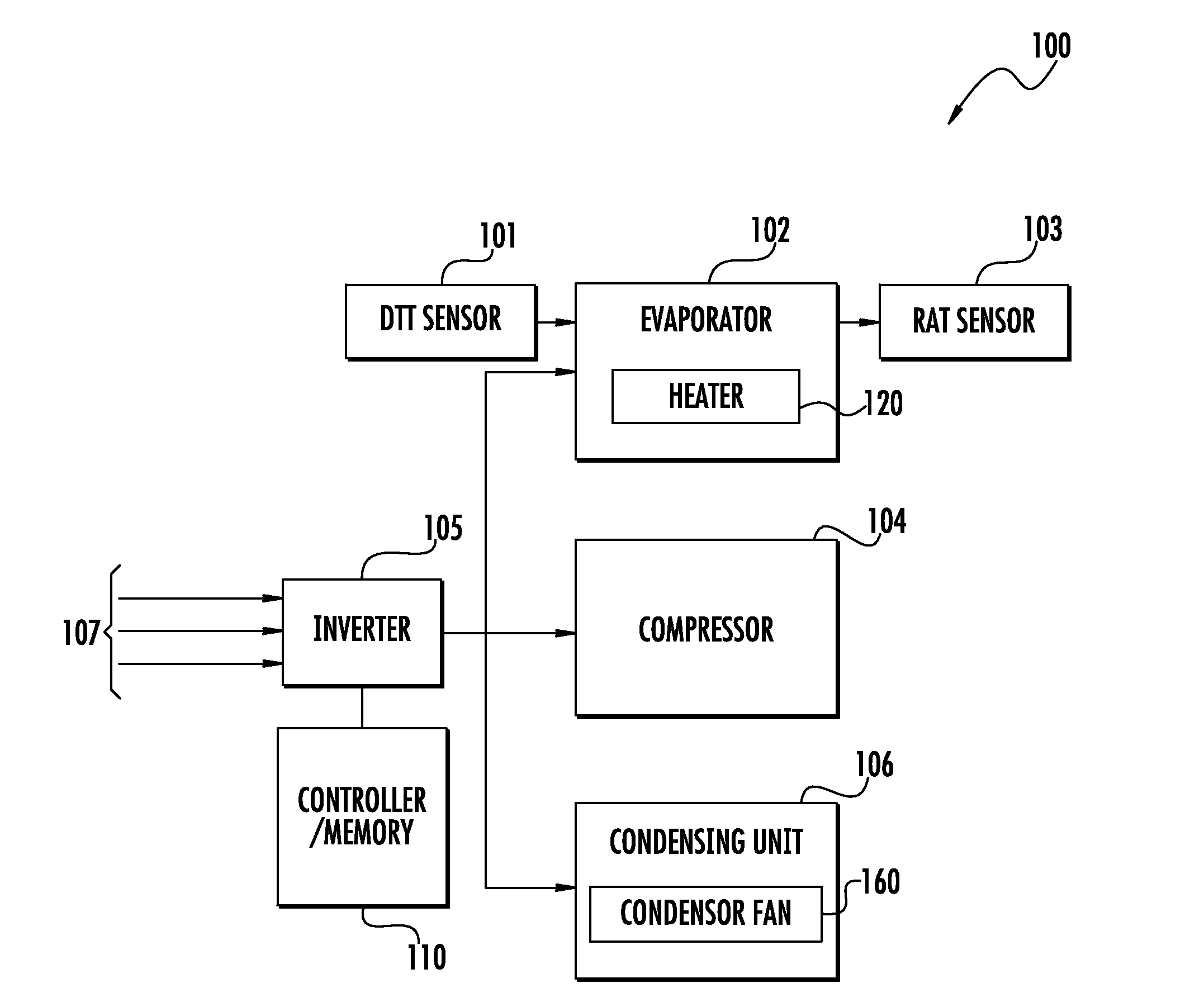
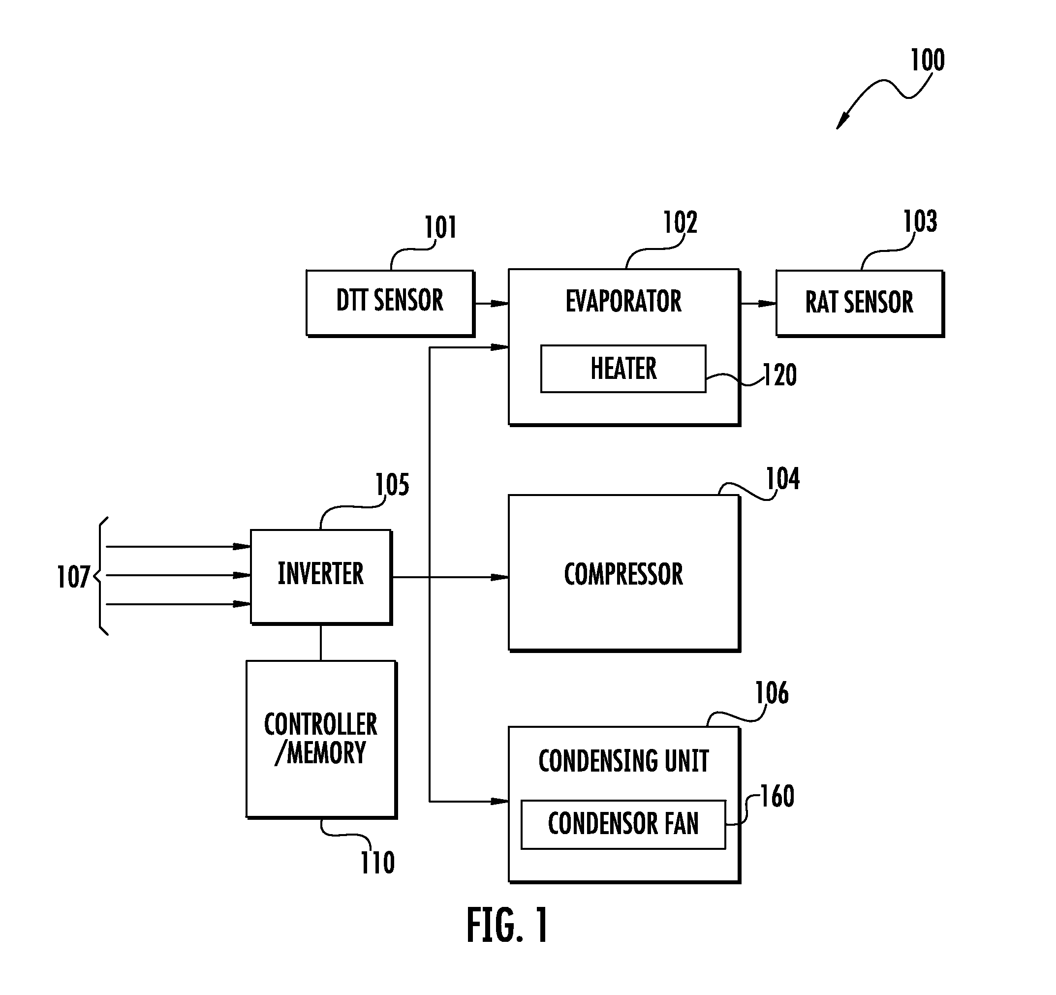
[0013]Embodiments of methods and systems of transport container refrigeration control and defrost operations are described herein in detail. Technical effects and benefits of such methods include limiting compressor liquid flow through novel starting sequences.

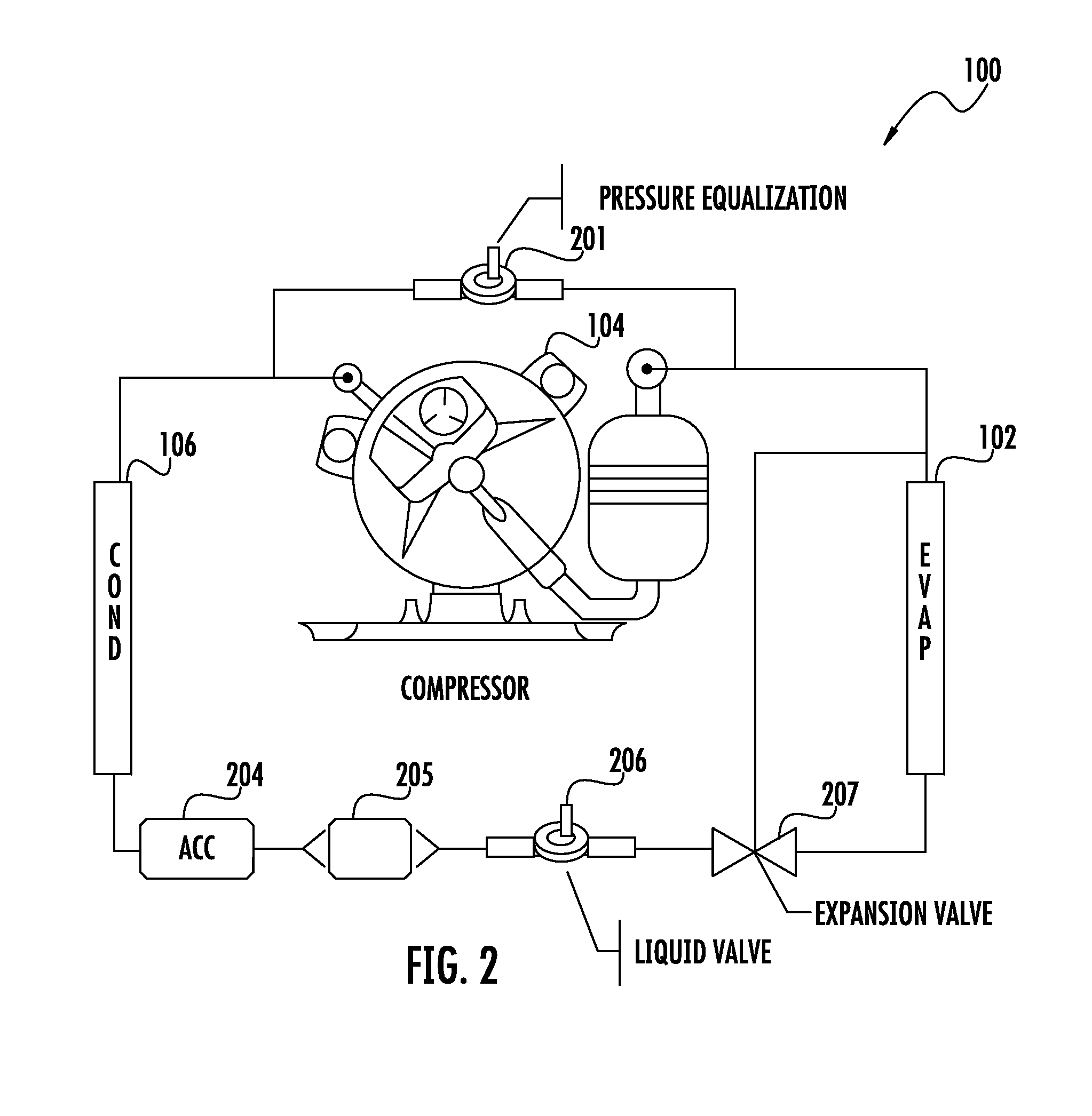
[0014]Turning to FIG. 1, a simplified representation of a refrigeration system 100 for transport containers is illustrated. Additional components included within the system 100 are omitted from FIG. 1 for the purpose of clarity only, and are described in detail with reference to FIG. 2. The system 100 may be electrically powered. For example, the system 100 may be in electrical communication with a power medium 107. The power medium 107 may be supplied through a vehicle powered generator, AC mains, three-phase power grid, or any other suitable power supply.

[0015]The system 100 includes inverter 105 in communication with the power medium 107. The inverter 105 may convert power supplied through power medium 107 into power usable...


PUM


Abstract

A method of refrigeration control through a refrigeration system of a refrigerated transport container includes performing a defrost cycle on the refrigeration system by activating a heat source; and restarting the refrigeration system after the defrost cycle has completed, wherein restarting the refrigeration system includes performing a liquid slugging avoidance process including: initiating a compressor of the refrigeration system at a speed; opening a pressure equalization valve in parallel with the compressor in response to the initiating; opening a liquid valve in series between a condenser and an evaporator after opening of the pressure equalization valve; and closing the pressure equalization valve after a period of time.

Description

FIELD OF INVENTION[0001]The subject matter disclosed herein relates generally to the field of refrigeration, and more particularly to methods and systems of defrosting a transport container refrigeration system and avoiding compressor slugging.DESCRIPTION OF RELATED ART[0002]Generally, in direct drive transport refrigeration, a road compressor is directly coupled to a vehicle. The associated refrigerating system is relatively simple with few valves that do not protect the compressor against liquid flow back. Because these systems use hot gas defrost technology with a shunted condenser and expansion valve, the compressor may systematically suck liquid from the evaporator during and after the hot gas defrost. Accordingly, compressor damage and premature failure is possible. Furthermore, in direct drive applications subsequent defrost-timings are non-optimal. Thus, the art would well receive improvements in defrosting transport container refrigeration systems and avoiding compressor sl...

Claims


Application Information

Patent Timeline
Patent Type & Authority Applications(United States)
IPC IPC(8): F25D21/00
CPCF25B47/02F25B49/02F25B2500/26F25B2500/28F25D21/08F25B2600/025F25B2600/0261F25B2600/112F25B2600/23F25B2600/2519F25B2700/2117F25B2700/21171Y02B30/70F25B41/20F25D21/002
Inventor PEYAUD, FABIENNEGOUX, JEANPHILIPPECHOQUART, VIRGINIE
Owner CARRIER CORP
Why Eureka
Try Eureka