Stovepipe Damper System

Inactive Publication Date: 2014-05-22
REED ANDREW C
View PDF4 Cites 2 Cited by
  • Summary
  • Abstract
  • Description
  • Claims
  • Application Information

AI Technical Summary

Benefits of technology

[0008]The present invention overcomes the problems associated with the prior art by providing a wood stove damper assembly that is resistant to failure associated with heat cycle fatigue. The invention maintains engagement between the damper assembly and the c

Problems solved by technology

Prior art stovepipe dampers suffer some serious drawbacks.
These heat cycles cause the spring to relax (and sometimes totally fail) such that the force applied by the spring between the handle and the stovepipe is insufficient to keep t

Method used


Image

  • Stovepipe Damper System
  • Stovepipe Damper System
  • Stovepipe Damper System

Examples


Embodiment Construction

[0026]The present invention overcomes the problems associated with the prior art by providing a wood stove damper that is resistant to failure associated with heat cycle fatigue. In the following description, numerous specific details are set forth (e.g. fastener types, etc.) in order to provide a thorough understanding of the invention. Those skilled in the art will recognize, however, that the invention may be practiced apart from these specific details. In other instances, details of well-known manufacturing practices (e.g., metal stamping, casting, etc.) and components have been omitted, so as not to unnecessarily obscure the present invention.

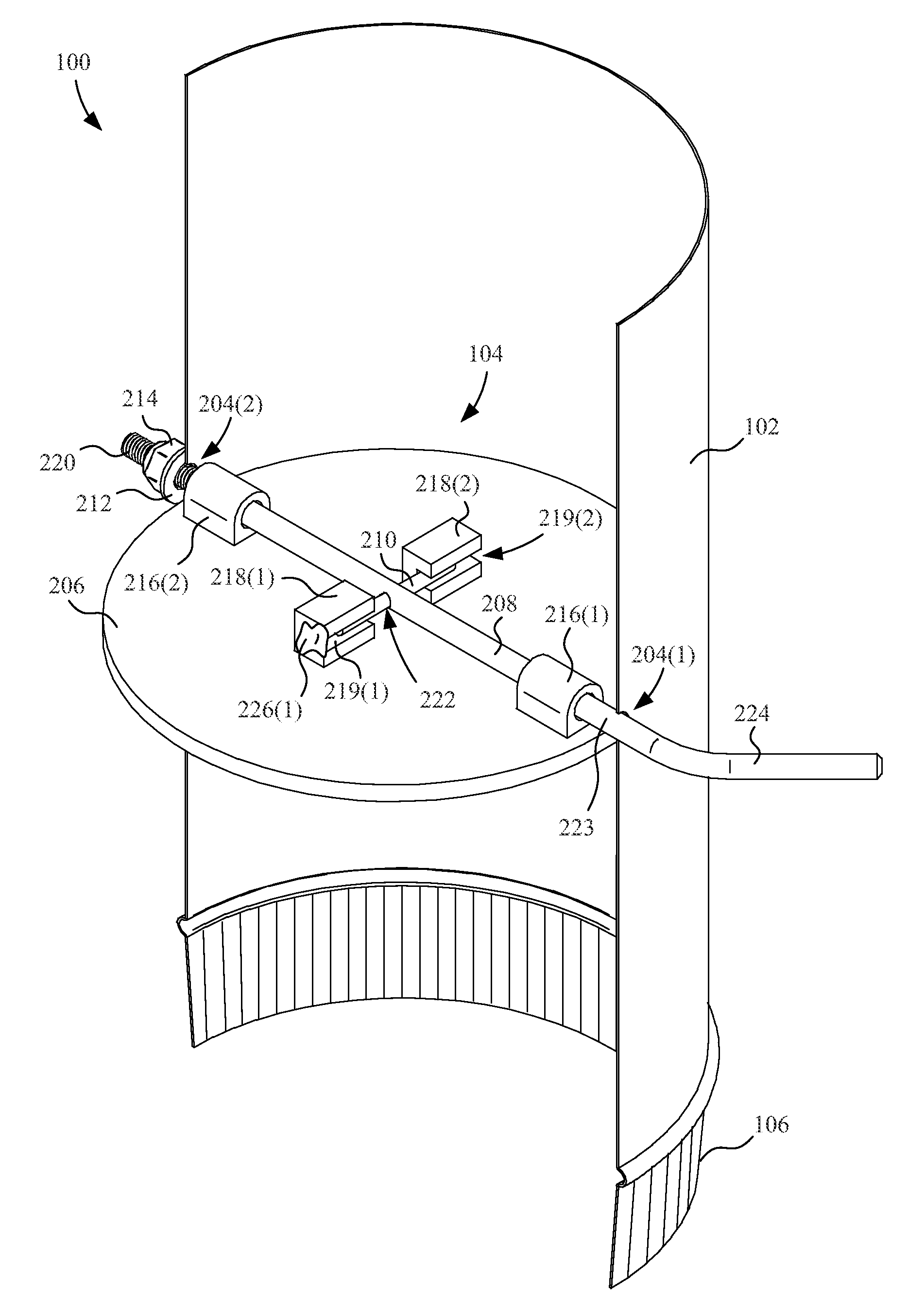
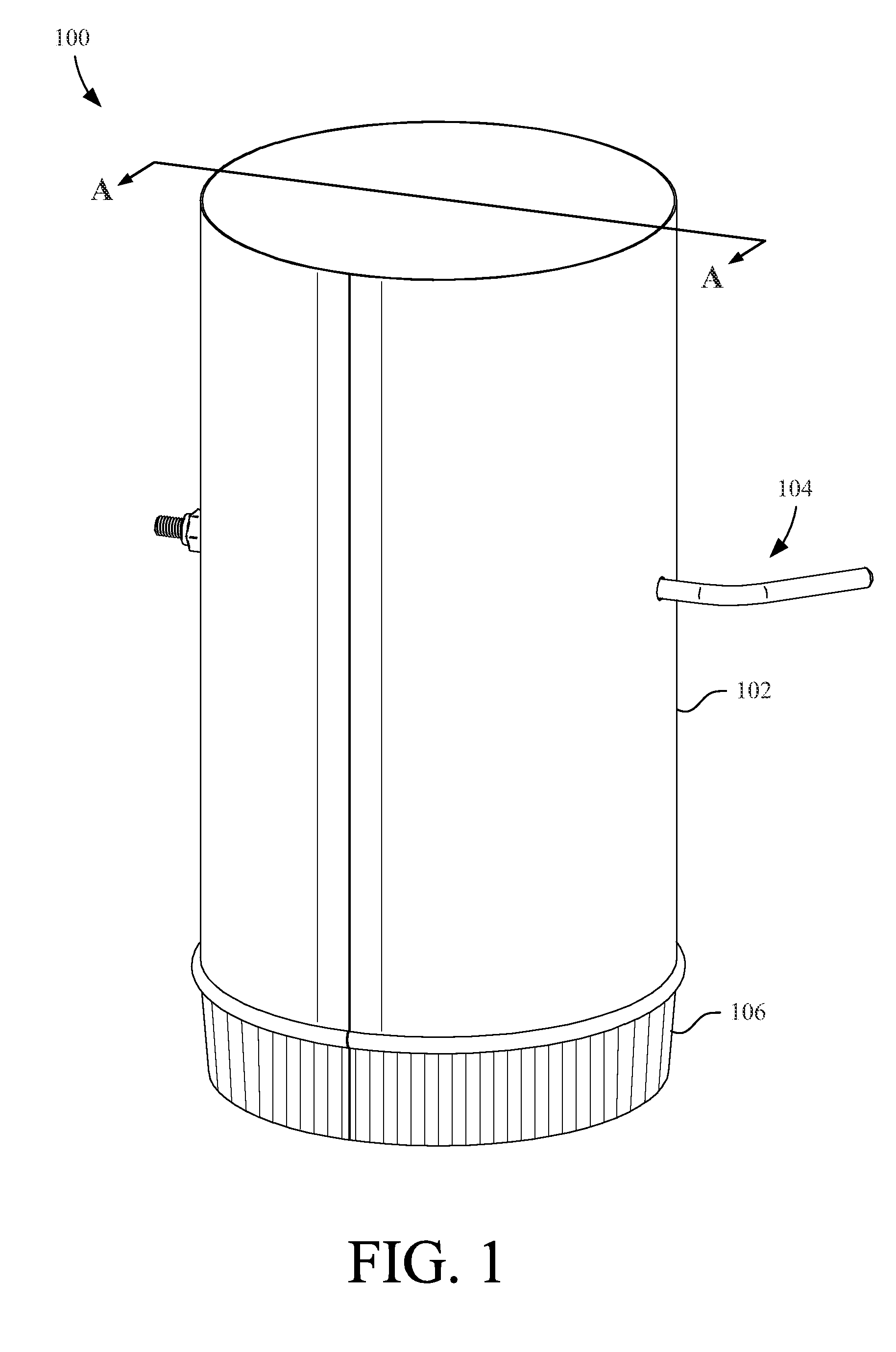
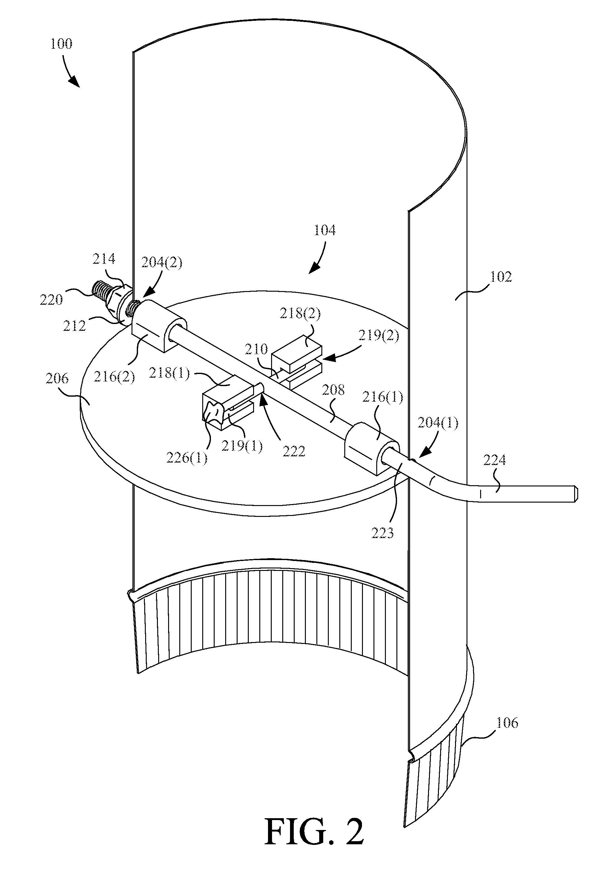
[0027]FIG. 1 shows a perspective view of a wood stove damper system 100 according to one embodiment of the present invention. Damper system 100 includes a section of a metal stovepipe 102 and a damper assembly 104 installed in the stovepipe 102. Only portions of the damper assembly 104 located outside of the stovepipe 102 are shown in FIG....


PUM


Abstract

A wood stove damper assembly includes a damper plate, a through shaft, and a cross shaft. The damper plate includes a plurality of risers and a plurality of through shaft guides. The through shaft includes a bore and the cross shaft is configured to engage the bore and the risers. The cross shaft is inserted through the bore in the through shaft such that the cross shaft engages the risers when installed. The damper assembly also includes a fastener applied to the end of the through shaft. When installed in a chimney pipe, the fastener is tightened to pull the through shaft, which pulls the cross shaft against the risers, which pulls the edge of the damper plate against the interior of the chimney pipe to hold the damper plate in any position. Methods for manufacturing and installing a damper assembly are also disclosed.

Description

CROSS-REFERENCE TO RELATED APPLICATIONS[0001]This application claims the benefit of co-pending U.S. Provisional Patent Application Ser. No. 61 / 728,527, filed on Nov. 20, 2012 by the same inventor and entitled “Stovepipe Damper System”, which is incorporated by reference herein in its entirety.BACKGROUND OF THE INVENTION[0002]1. Field of the Invention[0003]This invention relates generally to dampers, and more particularly to dampers for stovepipes of wood stoves.[0004]2. Description of the Background Art[0005]A prior art stovepipe damper includes a damper blade, a through shaft, and a coil spring. The through shaft has a handle and a U-shaped portion that engages the damper blade. The spring exerts a force between the outside of the stovepipe and the handle which maintains the engagement between the U-shaped portion and the damper blade and also maintains the damper blade in the damping position set by a user.[0006]Prior art stovepipe dampers suffer some serious drawbacks. Over time,...

Claims


Application Information

Patent Timeline
IPC IPC(8): F23L13/02
CPCF23L11/00F23L13/02
Inventor REED, ANDREW C.
Owner REED ANDREW C
Why Eureka
Try Eureka