Progressive-acting suspension device / damper for vehicles

a technology of suspension device and vehicle, which is applied in the direction of vibration dampers, mechanical devices, and resilient suspensions, etc., can solve the problems of increasing the volume and weight of the suspension, the geometry of the vehicle, and the addition of leverage, so as to increase the reaction and stiffness of the suspension

Inactive Publication Date: 2014-05-22
BETA ENG
View PDF4 Cites 0 Cited by
  • Summary
  • Abstract
  • Description
  • Claims
  • Application Information

AI Technical Summary

Benefits of technology

[0006]The present invention has been designed to overcome at least the drawbacks of the known technique and with the aims of simplifying the structure of a suspension device for vehicles, avoiding mechanical springs, as well as reducing volumes and weight of the device all performances being equal.
[0007]A further object of the invention is to propose, specifically, a new and original suspension device having progressive effect without having to recur to bulky linkages, meaning to increase its reaction and stiffness as of the load it is subjected to increases from time to time, usable according to different arrangements within the scope of a vehicle and designed to advantageously reduce the spaces it occupies so to allow new and more suitable geometries in the manufacturing of vehicles, particularly the two wheel vehicles.
[0012]Preferably the two units are coaxially integrated in a same body with a member in common able to activate both the hydraulic unit and the pneumatic damping unit in response to the load the suspension is subjected to. The common member is the piston rod that follows, on the one hand, the piston movements and carries the pressing head operating onto the air cushion having progressive damping effect on the other hand.
[0013]Substantially, as a whole the pneumatic damping unit allows to give the suspension device a progressive effect of oscillation smoothing of a member of a vehicle to be damped in response to the ground conditions it has to travel through, and this without recurring to bulky leverages and with the advantage of increasing reaction and stiffness of the suspension as the load it is subjected to increases from time to time.

Problems solved by technology

However, the adoption of an additional leverage is prone to disadvantageously increase complexity, volumes and weight of the suspension, as well as the geometry of the vehicle.

Method used


Image

  • Progressive-acting suspension device / damper for vehicles
  • Progressive-acting suspension device / damper for vehicles
  • Progressive-acting suspension device / damper for vehicles

Examples


Embodiment Construction

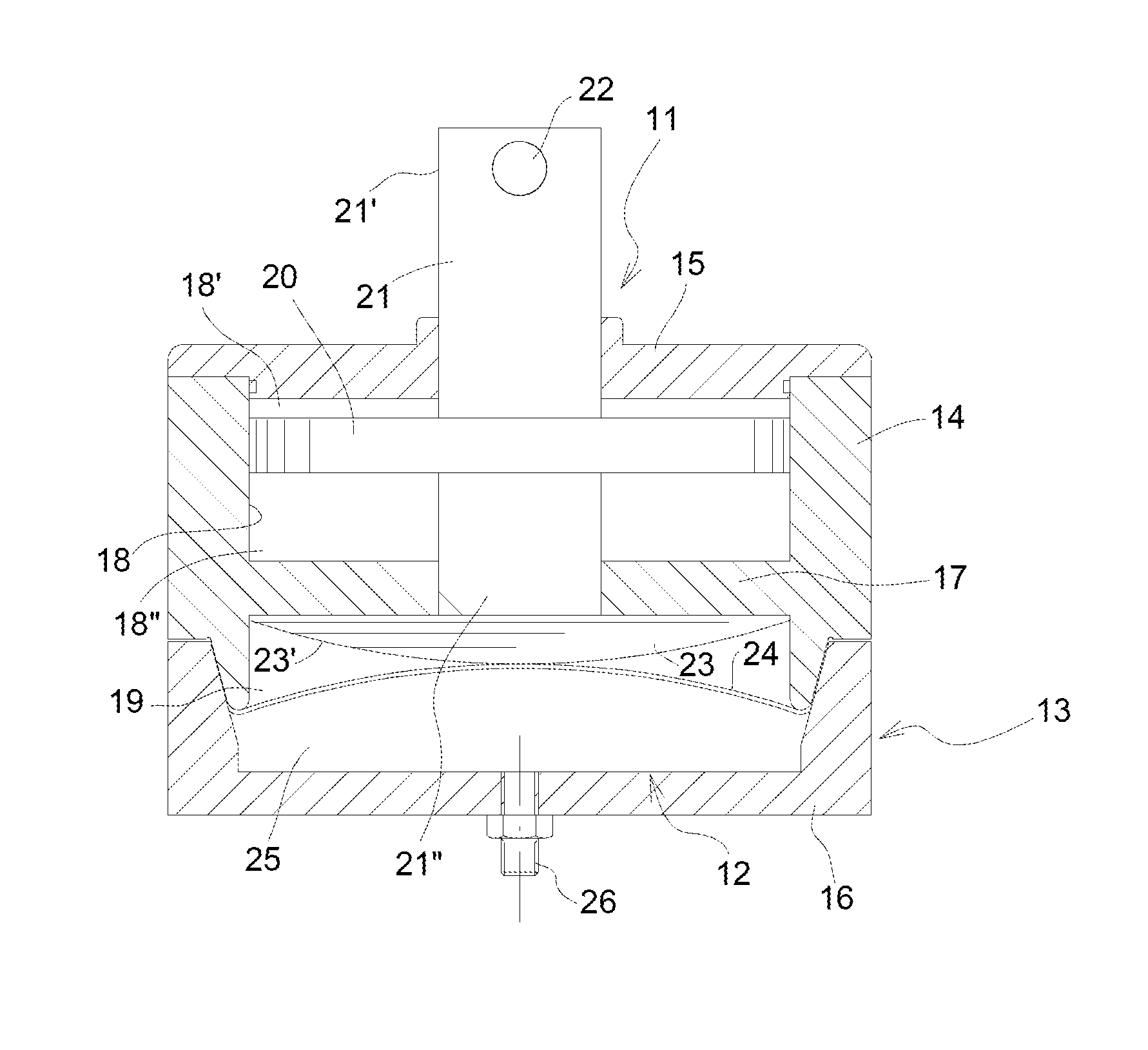
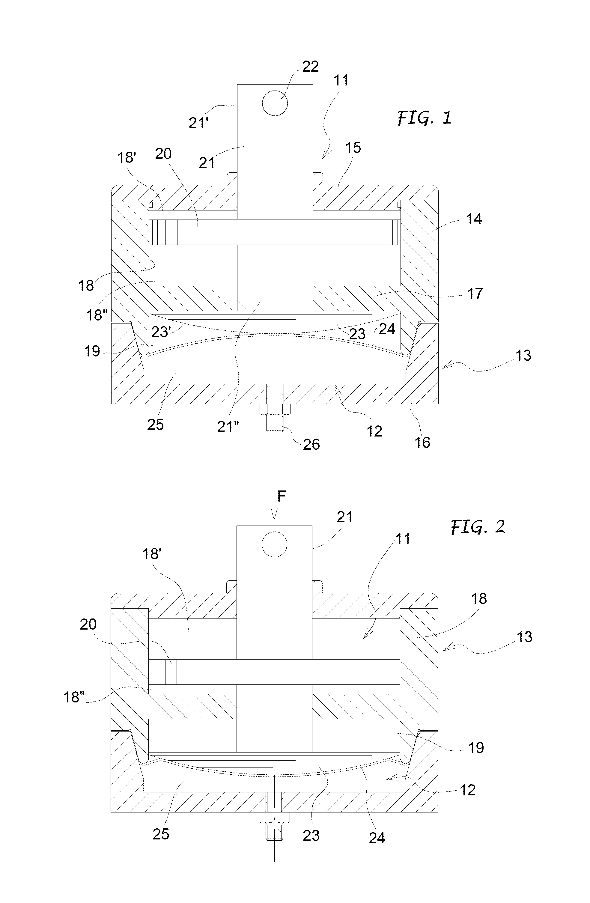
[0018]The device according to the invention essentially comprises a hydraulic damping unit 11 and a pneumatic damping unit 12. In the exemplary embodiment shown in FIGS. 1 and 2, the two hydraulic and pneumatic units 11, 12 are integrated in a same body 13, preferably coaxially.

[0019]Then such a body 13 can comprise a preferably cylindrical liner 14, whose opposite ends are closed by head 15 and bottom 16 flanges, respectively. Said liner and said flanges are coupled with the interposition of sealing gaskets. Further, inside said liner 14 an intermediate partition 17 parallel to the head and bottom flanges 15, 16 and defining with them a first chamber 18 and a second chamber 19 is provided.

[0020]In the illustrated example, the first chamber is provided to be part of the hydraulic damping unit 11, whereas the second chamber 19 is part of the pneumatic damping unit 12.

[0021]In the first chamber 18 a piston 20 is accommodated and movable and it is carried by a rod 21 which is guided an...


PUM


Abstract

A suspension device / damper for vehicles is provided, which includes a hydraulic damping unit (11) substantially acting linearly having a piston (20) provided with a guide rod (21) and operating in a chamber (16) containing an incompressible fluid. With the hydraulic damping unit (11) is combined a pneumatic damping unit (12) having progressive effect, activated by and collaborating with the damping action of said hydraulic unit. The pneumatic damping unit (12) includes a pressing head (23) operating through an elastic membrane (24) onto an air cushion (25) with a variable effect in response to the movements of the piston (20) in the chamber containing the incompressible fluid of the hydraulic damping unit (11).

Description

FIELD OF THE INVENTION[0001]The present invention relates in general to both four- and two-wheel vehicles, and specifically relates to a suspension device / damper for such vehicles.STATE OF THE ART[0002]The wheels of vehicles, specifically motorbikes and similarly bikes, can be supported by means of damper suspensions intended to absorb impacts and reduce abrupt load increases on wheels due both to the unevenness of the ground the vehicle is running and the landing after a possible jump as it can occur, for example, with trail motorbikes and / or similarly with trail bikes.[0003]A suspension device / damper can be of spring type as disclosed, for example, by the documents U.S. Pat. No. 4,360,214 and EP 1 223 101 or hydraulic type as disclosed, for example, by the document EP 1 535 828 or hydro pneumatic, each one with features, performances and also drawbacks well known to the field technicians.[0004]Then specifically, in the two wheels vehicles, for example, the suspension is generally ...

Claims


Application Information

Patent Timeline
Patent Type & Authority Applications(United States)
IPC IPC(8): F16F9/096B60G15/06B60G15/12F16F13/20
CPCF16F9/096F16F13/20B60G15/12B60G15/06
Inventor BELLANDI, GIUSEPPEMAFEZZONI, GRAZIANO
Owner BETA ENG
Why Eureka
Try Eureka