Rotating wavelength conversion element

Active Publication Date: 2014-05-22
BARCO NV
View PDF4 Cites 38 Cited by
  • Summary
  • Abstract
  • Description
  • Claims
  • Application Information

AI Technical Summary

Benefits of technology

[0011]An object of the present invention is to provide an alternative illumination device and method for providing high brightness colored or multicolored light. In particular an object of the invention is to provide an illumination device and method that suffers l

Problems solved by technology

Lamps are expensive and often do not last long enough.
However conversion to solid state lighting still remains a challenge.
A limitation still lies in the heat dissipation of the phosphors.
A phosphor layer emits light rather in a lambertian way, which makes the light difficult to be captured and collimated.
In this small spot, high energy dissipation will saturate the phosphor at a certain level, with brightness clipping and phosphor layer d

Method used


Image

  • Rotating wavelength conversion element
  • Rotating wavelength conversion element
  • Rotating wavelength conversion element

Examples


Example

DEFINITIONS

[0053]The term “wavelength conversion material” as used herein relates to photoluminescence materials. The term “photoluminescence” as used herein relates to materials which encompass both fluorescence and / or phosphorescence materials, for instance phosphors and quantum dots are within the scope of this definition. The term “phosphor” as used herein relates to any material which is able to emit light by fluorescence, phosphorescence or more generally by photoluminescence. Thus in the following reference to photoluminescent wheel includes individual and separate reference to phosphorescent or fluorescent wheel just as reference to photoluminescent material includes individual and separate reference to phosphorescent or fluorescent material.

[0054]Reference to a “region” of photoluminescent material refers to an area which comprises such material area covered by such a material.

DETAILED DESCRIPTION OF PREFERRED EMBODIMENTS

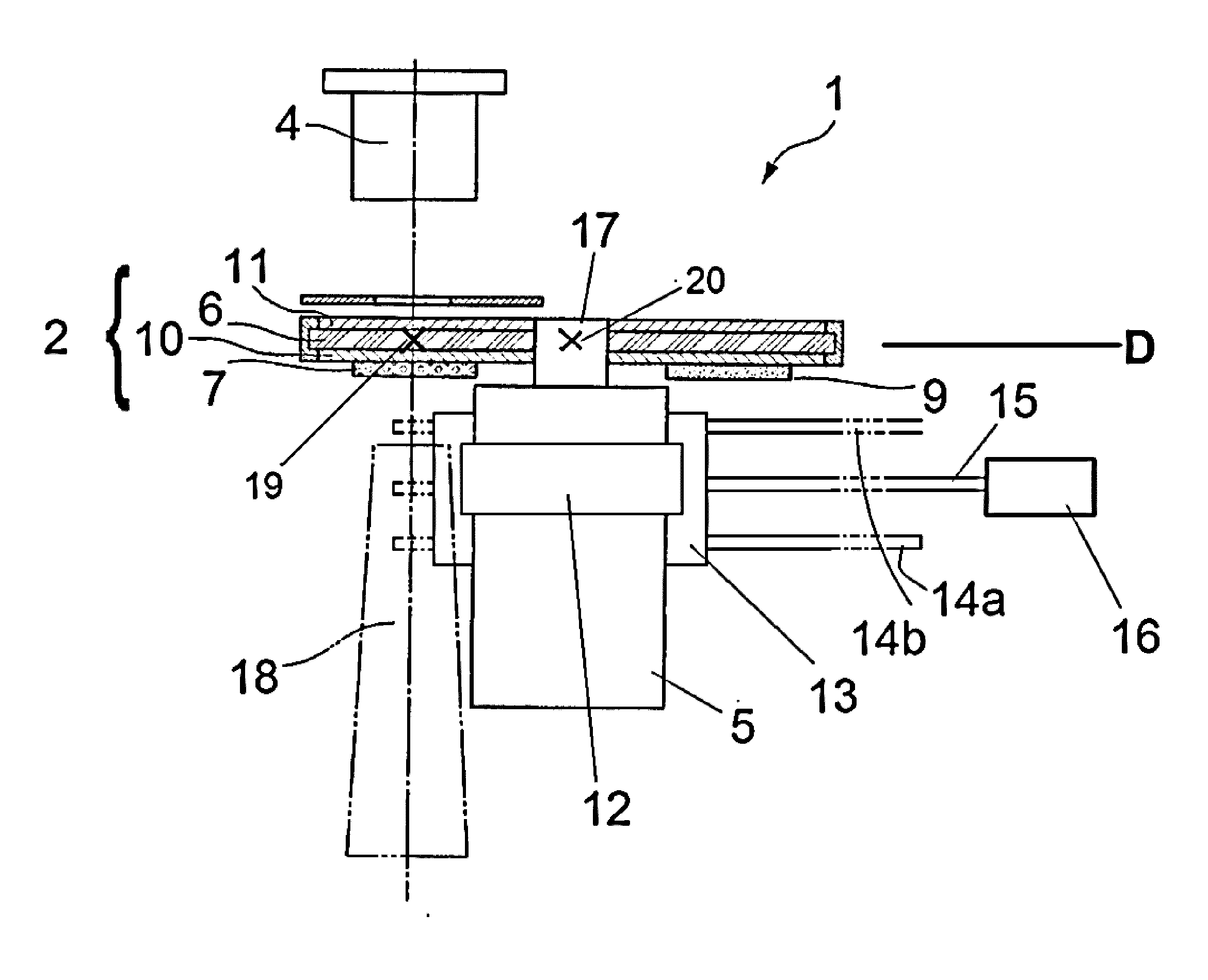
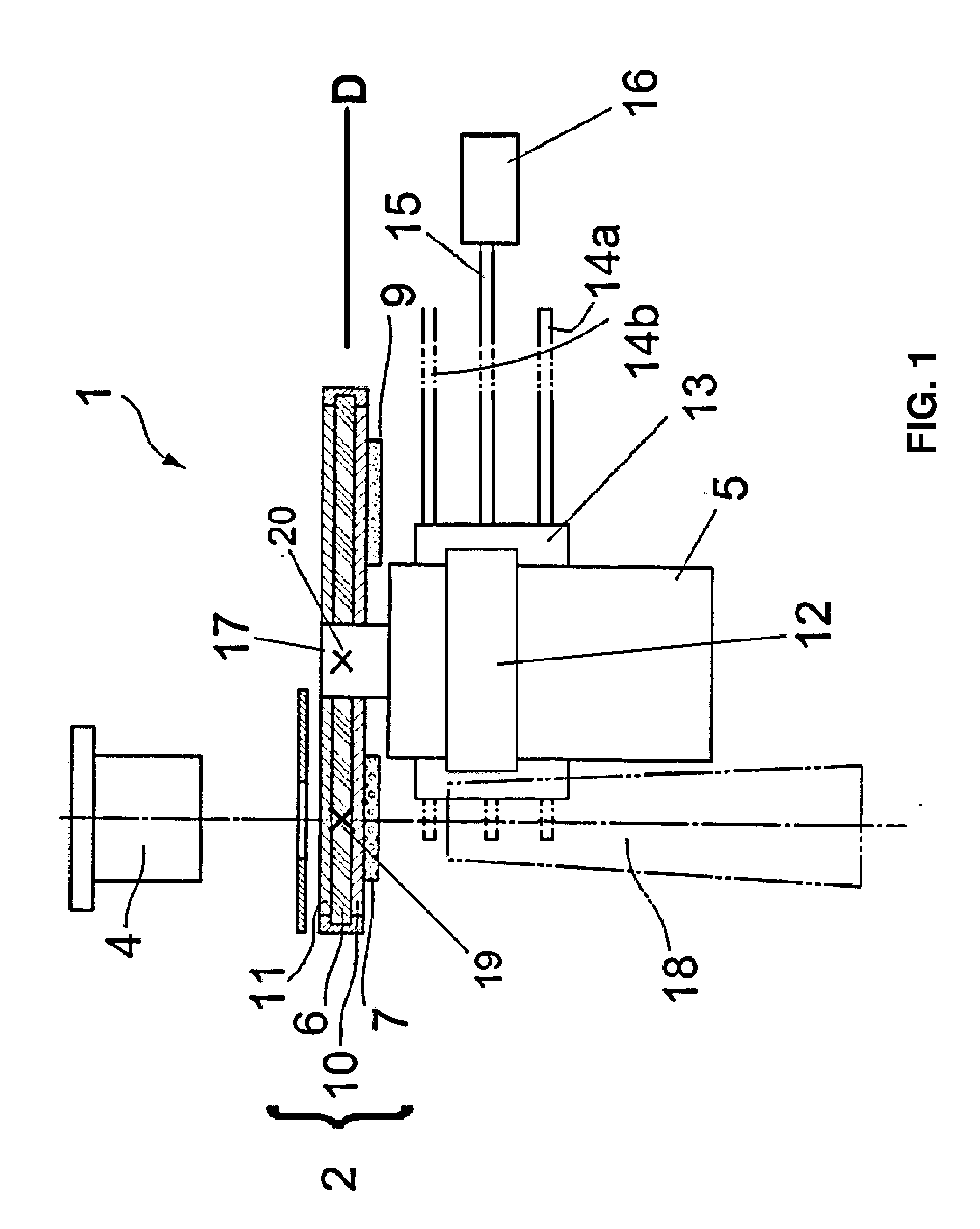
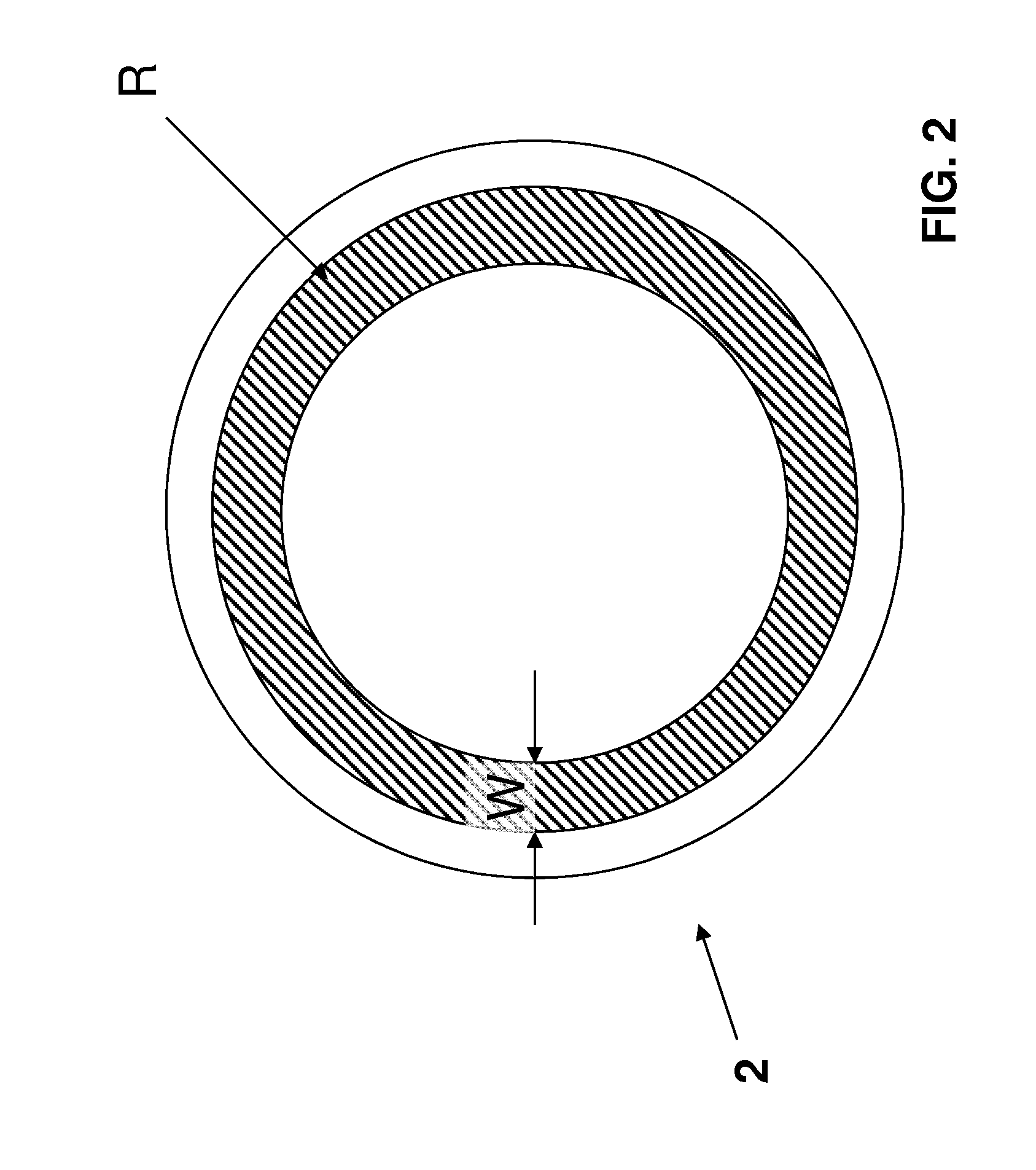
[0055]The present invention will be described with re...


PUM


Abstract

A method and apparatus is described for producing high brightness, e.g. multicolor light, whereby a region of a wavelength conversion element and a light source producing excitation light are moved relative to each other so that said region is exposed to the excitation light at different times and in a progressive movement that scans across a part of the entire surface of the wavelength conversion element. The wavelength conversion element can be cooled by air or with a liquid.

Description

FIELD OF THE INVENTION[0001]The present invention relates to an illumination device and method for providing high brightness multicolor light as well as to a projection device including the illumination device.BACKGROUND OF THE INVENTION[0002]For the illumination of digital projection systems, solid state lighting could be a preferred method. Typically a light source is combined with an imaging system which yields the actual image. The brightness of the projection system is mainly depending on the power and the nature of the light source. Up to now lamps have been used more or less exclusively. For low brightness systems, UHP lamps are used, for high brightness systems, Xenon lamps are used. Lamps are expensive and often do not last long enough. However conversion to solid state lighting still remains a challenge.[0003]LED illumination technology has been used successfully for low brightness systems. Typically LED illumination replaces the UHP lamps for low brightness systems up to ...

Claims


Application Information

Patent Timeline
IPC IPC(8): F21V14/08F21V9/16F21V29/00F21V13/08
CPCF21V14/08F21V9/16F21V29/30F21V13/08F21V7/26F21V9/45F21V13/14G03B21/16G03B21/204G03B21/208H04N9/3114H04N9/3144H04N9/3158F21S10/007F21S10/02G03B21/26F21V29/56
Inventor GERETS, PETERCHARLIER, OLIVERMAES, DIRK
Owner BARCO NV
Why Eureka
Try Eureka