Resin injection apparatus for drilling apparatus for installing a ground anchor

a technology for injecting equipment and rock formations, which is applied in the direction of anchoring bolts, earthwork drilling and mining, mining structures, etc., can solve the problems of affecting the safety of work environment, affecting the effect of resin mixing, and affecting the safety of workers

Active Publication Date: 2014-05-22
GEOBRUGG AG
View PDF6 Cites 23 Cited by
  • Summary
  • Abstract
  • Description
  • Claims
  • Application Information

AI Technical Summary

Benefits of technology

[0028]a fluid injector provided in fluid communication with the hollow drill shaft of the rock drill, for injecting one or more resin fluids into the drill shaft wherein, in use, when a hole has been drilled in a rock strata, resin can be injected into the hole via the drill shaft prior to inserting a ground anchor.

Problems solved by technology

It has been estimated that 30%-35% of the rock anchors do not perform to specification and may represent some risk to the maintenance of a safe workplace environment (Galvin et al 2001).
The insertion of the bolt causes the plastic sheath of the cartridge to break.
Breaking the plastic sheath of the cartridge and mixing the resin components effectively can be problematic.
Many resin anchors are ineffective because the resin components are not mixed completely.
The shredded cartridge can interfere with the resin and catalyst mixing.
Poor mixing results in an inferior cured resin and results in poor bond strength between the bolt and drill hole wall.
Furthermore this method of installing resin anchors is complicated and time-consuming.
The method results in slow resin anchor installation and provides for workplace safety issues.
A disadvantage with this system is that the resin cartridge may prematurely rupture during transportation, or during the boring process, prior to completion of the boring process.
A further problem is that there may not be sufficient resin forced into the hole for securing the steel bolt.
However, because it is a dedicated machine it is very expensive for a mining business to incorporate into their fleet as it cannot perform any other function apart from ground support installation.
From the above description of several prior art methods of installing ground anchors it can be seen that the prior art systems utilised suffer from issues associated with at least resin stability and effective mixing of resin components once in use.
Various safety issues also arise.

Method used


Image

  • Resin injection apparatus for drilling apparatus for installing a ground anchor
  • Resin injection apparatus for drilling apparatus for installing a ground anchor
  • Resin injection apparatus for drilling apparatus for installing a ground anchor

Examples


second embodiment

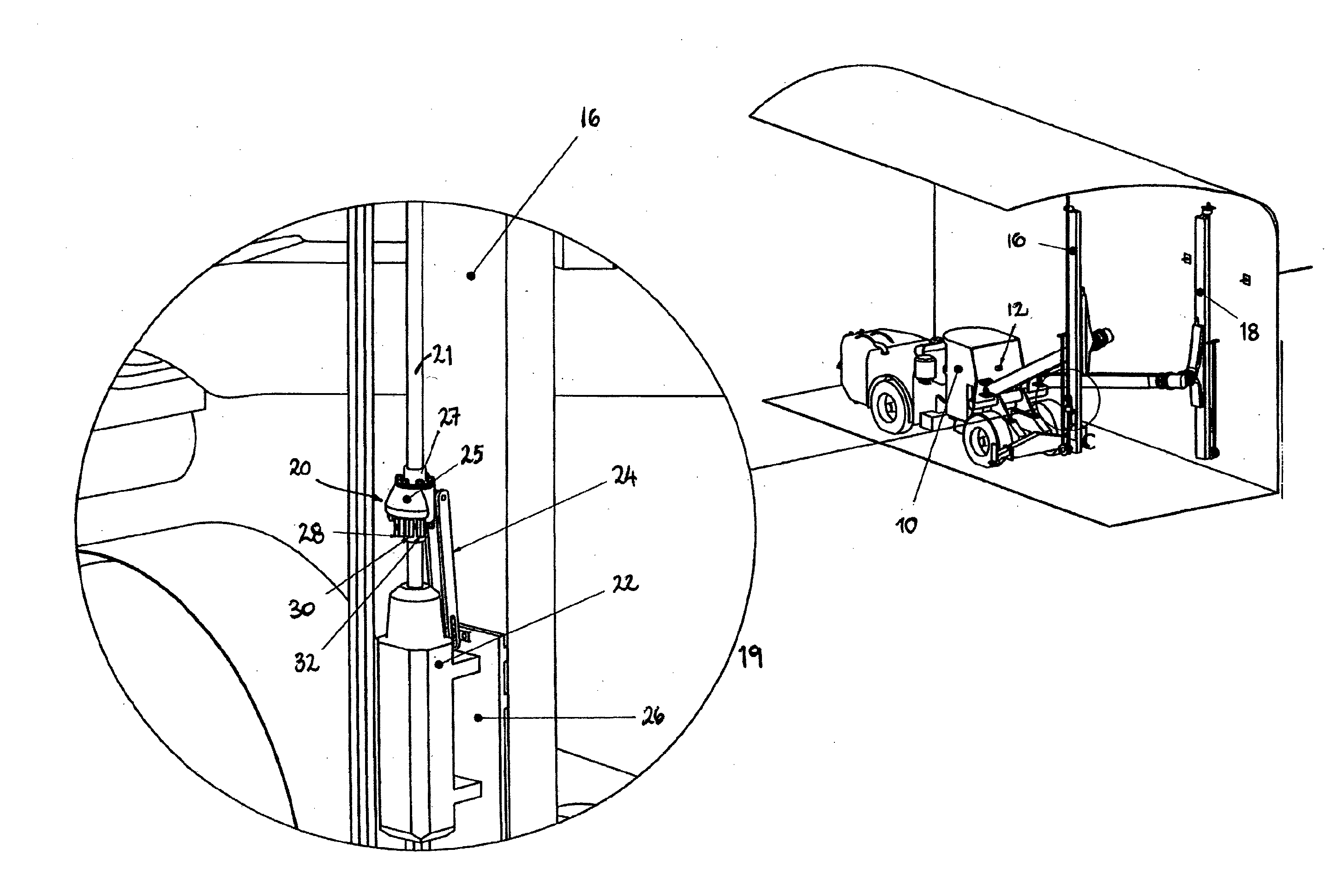
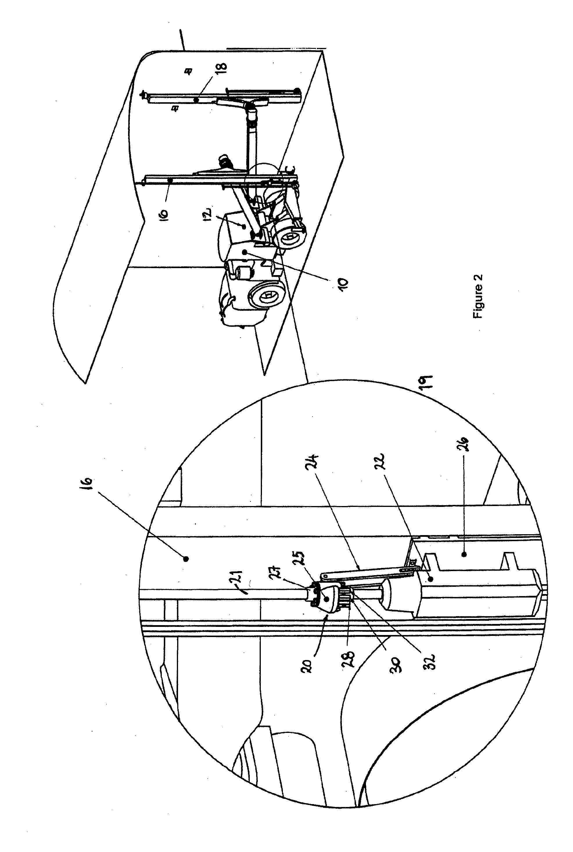
[0062]FIGS. 6 to 9 illustrate a fluid injector 51 employed in the fluid injection apparatus according to the present invention. The fluid injector 51 comprises a rotatable engaging means 52 for rotatably engaging a drill shaft 21 of a drilling apparatus. The rotatable engaging means 52 of this embodiment comprises first and second sealed bearings 53 and 54 which provide a fluid-tight seal about the outer surface of the couple 27 which couples the drill shaft 21 and the interior of the rotatable engaging means 52. The rotatable engaging means 52 further comprises an outer housing 55 enclosing a mixing chamber 56. Mixing chamber 56 is in fluid communication with a fluid injection port 57 (see FIG. 9) provided in the wall of the coupling 27 in the region enclosed within the rotatable engaging means 52 of the fluid injector 51.

[0063]The fluid injector 51 further comprises a valve manifold 58 which is provided on a wall of the outer housing 55 of the rotatable engaging means 52, as can b...

first embodiment

[0069]A locking bracket 69 (see FIG. 9) is provided on the outer housing 55 of the rotatable engaging means 52 for securing the fluid injector 51 and preventing it from rotating with the drill shaft 21 and coupling 27. A locking bar 24 (not shown), similar that employed in the first embodiment, is connected to the locking bracket 69.

[0070]Now that preferred embodiments of the invention have been described in detail, it will be apparent that the described embodiment provides a number of advantages over the prior art, including the following:[0071]i. The system provides a generally fast and efficient application of resin to the base of a hole through the drilling rigs normal drilling components i.e. the rock drill and drill bit, and with the aid of a fluid injector, chemical pumps, a control system for the control of resin chemical pump flow, feed retraction speed and automatic flushing / cleaning. Thereby providing an efficient, effective and economic alternative to the apparatus and m...


PUM


Abstract

A resin injection apparatus for use in connection with a drilling apparatus for installing ground anchors. The resin injection apparatus comprises a fluid injector, adapted to be connected in fluid communication with a hollow drill shaft of a drill rig. The fluid injector can be used to inject one or more resin fluids into the drill shaft wherein, in use, when a hole has been drilled in a rock stratum, resin can be injected into the hole via the drill shaft prior to inserting a ground anchor.

Description

FIELD OF THE INVENTION[0001]The present invention relates to a method and apparatus for injecting resin into a rock formation. In particular, the invention relates to a resin injection apparatus and method for injecting resin during the installation of ground anchors in ground / rock strata.BACKGROUND TO THE INVENTION[0002]In most underground mines, ground anchors form the basis of the primary roof and / or wall support systems within tunnels. To enforce a roof or wall, ground anchors can be installed mechanically or manually using resin, cement grout, friction anchors or point anchors or a combination of such. It has been estimated that 30%-35% of the rock anchors do not perform to specification and may represent some risk to the maintenance of a safe workplace environment (Galvin et al 2001).[0003]Typically the method for installing chemical anchors, otherwise known as resin anchors, first requires for a hole to be drilled into the roof or wall. Resin anchors comprise steel bolts / cabl...

Claims


Application Information

Patent Timeline
Patent Type & Authority Applications(United States)
IPC IPC(8): E21D20/02E21D20/00
CPCE21D20/028E21D20/003E21D20/025E21D21/00
Inventor BROWN, SHANE
Owner GEOBRUGG AG
Why Eureka
Try Eureka