Systems And Methods For Wireless Power System With Improved Performance and/or Ease of Use

a wireless power system and wireless technology, applied in the direction of electric devices, instruments, transportation and packaging, etc., can solve the problems of inefficient power transfer, inability to transfer electrical energy, inconvenient communication, etc., to facilitate communication and facilitate the deployment of the wired pair of resonators

Active Publication Date: 2014-05-22
WITRICITY CORP
View PDF9 Cites 278 Cited by
  • Summary
  • Abstract
  • Description
  • Claims
  • Application Information

AI Technical Summary

Benefits of technology

[0029]Furthermore, in certain embodiments, the length of capacitively loaded conducting material includes modular capacitive elements to adjustably load the conducting material according to the length of the wired electrical connection. This can enable a user to more easily deploy the wired pair of resonators to a desired arrangement and separation.
[0030]Furthermore, in certain embodiments, the wired electrical connection facilitates communication with circuitry within at least one of the resonators in the second pair in order to cause the circuitry to activate, deactivate, or adjust a property of at least one of the resonators in the second pair. Furthermore, for example, the wireless power network can include a controller configured to adjustably open or close the wired electrical connection between at least the resonators in the second pair. This controller can be implemented as a physical switch on the hybrid pair of resonators or through network electronics.

Problems solved by technology

Inefficient power transfer may be acceptable for data transmission but is not practical for transferring electrical energy for the purpose of doing work, such as for powering or charging electrical devices.
Inefficient power transfer may not be preferred either because insufficient power may be transferred in order for a device to operate correctly, or because it will waste energy which is lost during transmission / reception.
However, these directed radiation schemes may require an uninterruptible line-of-sight and potentially complicated tracking and steering mechanisms in the case of mobile transmitters and / or receivers.
Furthermore, in certain embodiments, the resonators in the second pair are separated by a lossy barrier that substantially reduces wireless power transfer between the resonators in the second pair but does not substantially reduce the wired power transfer between the resonators in the second pair.

Method used


Image

  • Systems And Methods For Wireless Power System With Improved Performance and/or Ease of Use
  • Systems And Methods For Wireless Power System With Improved Performance and/or Ease of Use
  • Systems And Methods For Wireless Power System With Improved Performance and/or Ease of Use

Examples


Embodiment Construction

[0122]As described above, this disclosure relates to wireless energy transfer using coupled electromagnetic resonators. However, such energy transfer is not restricted to electromagnetic resonators, and the wireless energy transfer systems described herein are more general and may be implemented using a wide variety of resonators and resonant objects. Therefore, we first describe the general technique, and then disclose electromagnetic examples for wireless energy transfer.

[0123]Resonators

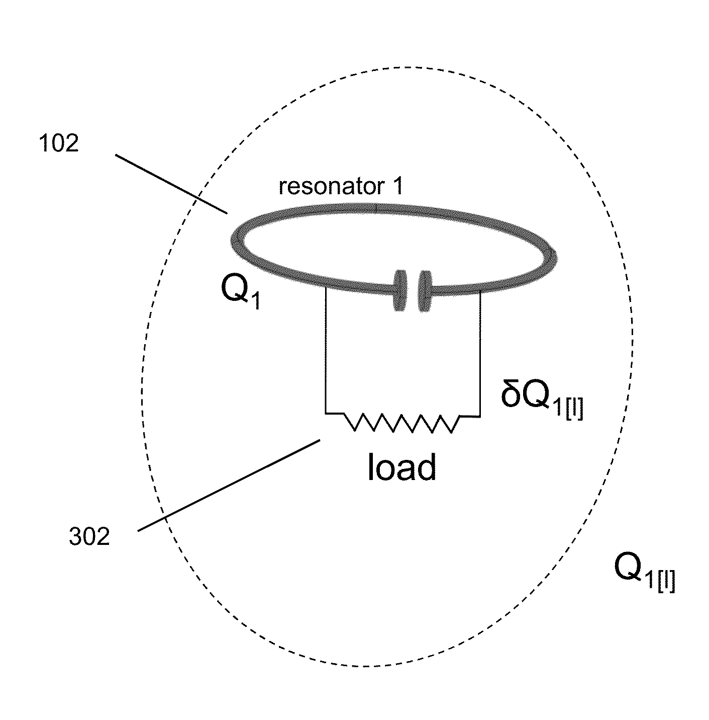
[0124]A resonator may be defined as a system that can store energy in at least two different forms, and where the stored energy is oscillating between the two forms. The resonance has a specific oscillation mode with a resonant (modal) frequency, f, and a resonant (modal) field. The angular resonant frequency, ω, may be defined as ω=2πf, the resonant wavelength, λ, may be defined as λ=c / f, where c is the speed of light, and the resonant period, T, may be defined as T=1 / f=2π / ω. In the absence of los...


PUM

PropertyMeasurementUnit
angleaaaaaaaaaa
angleaaaaaaaaaa
angleaaaaaaaaaa

Abstract

A device for testing a wireless power network is disclosed. The network includes at least one power source, at least one load, and multiple resonators configured to couple wireless power from the at least one power source to the at least one load. The device includes: a user interface for receiving input from a user and providing information to the user; a measurement module for measuring, whether directly or indirectly, at least one operational characteristic of the wireless power network and information about the geometric arrangement of the multiple resonators in the wireless power network; a memory for storing design specifications about the wireless power network; and an electronic processor configured to calculate information about a performance of the wireless power network based on the measured operational characteristic, the information about the geometric arrangement of the multiple resonators, and the stored design specifications, and further configured to provide the performance information to the user through the user interface.

Description

CROSS REFERENCE TO RELATED APPLICATIONS[0001]This application claims priority under 35 U.S.C. §119(e) to U.S. Provisional Application No. 61 / 727,260 filed Nov. 16, 2012 and entitled “Systems and Methods for Wireless Power System with Improved Efficiency”.BACKGROUND[0002]1. Field[0003]This disclosure relates to wireless energy transfer to power devices, also referred to as wireless power transmission.[0004]2. Description of the Related Art[0005]Energy or power may be transferred wirelessly using a variety of known radiative, or far-field, and non-radiative, or near-field, techniques as detailed, for example, in commonly owned U.S. patent application Ser. No. 12 / 613,686 published on May 6, 2010 as US 2010 / 010909445 and entitled “Wireless Energy Transfer Systems,” U.S. patent application Ser. No. 12 / 860,375 published on Dec. 9, 2010 as 2010 / 0308939 and entitled “Integrated Resonator-Shield Structures,” U.S. patent application Ser. No. 13 / 222,915 published on Mar. 15, 2012 as 2012 / 00623...

Claims


Application Information

Patent Timeline
Patent Type & Authority Applications(United States)
IPC IPC(8): G01R31/08H01F38/14
CPCH04B5/0037H04B5/0075H01F38/14H02J50/12H02J50/001H02J50/50H02J50/005H02J50/70
Inventor JOHN, MICHAEL SASHAHALL, KATHERINE L.KULIKOWSKI, KONRAD J.KESLER, MORRIS P.KURS, ANDRE B.ROY, ARUNANSHU M.GUCKAYA, GOZDE
Owner WITRICITY CORP
Why Eureka
Try Eureka