Buffer assembly of vacuum molding and cutting machine

a vacuum molding and cutting machine technology, applied in the direction of shock absorbers, manufacturing tools, presses, etc., can solve the problems of inability to balance the cutting edge is damaged or the desired object is not thoroughly cut, and the force exerted on each corner cannot be controlled effectively, so as to improve the cutting effect, buffer the impact force of the die cutting tool, and improve the cutting quality.

Active Publication Date: 2014-05-29
CHENG MEI MACHINE
View PDF4 Cites 1 Cited by
  • Summary
  • Abstract
  • Description
  • Claims
  • Application Information

AI Technical Summary

Benefits of technology

[0007]Therefore, it is a primary objective of the present invention to overcome the problems of the prior art by providing a buffer assembly of a vacuum molding and cutting machine capable of regulating the parallelism between a die cutting tool and a sheet automatically in a cutting process to improve the cutting effect, so as to improve the cutting quality significantly. Since the present invention can buffer the impact force of the die cutting tool effectively, therefore the service life of the die cutting tool can be extended.
[0008]To achieve the aforementioned objectives, the present invention provides a buffer assembly of a vacuum molding and cutting machine for buffering the impact force produced by punching a die cutting tool onto a sheet with a cutting thickness of 0.1 mm-0.5 mm, such that a blade of the die cutting tool cuts the sheet uniformly, comprising: a lower mold base, disposed under the die cutting tool, and having at least four installing holes formed around the periphery of the lower mold base, and the installing holes being arranged in pairs; at least four hydraulic elements, disposed in the installing holes respectively, and having a piston plunger installed at the top of each hydraulic element; and a movable plate, disposed above the lower mold base, and having a plurality of slots corresponding to the installing holes respectively, such that the piston plunger of each hydraulic element can be placed in each corresponding slot to prop the movable plate, and a predetermined distance is defined between the movable plate and the lower mold base. Wherein, the predetermined distance falls within a range of 0.5 mm-3 mm. During use, the movable plate is impacted by the die cutting tool, and the piston plungers are provided for absorbing the impact force, such that the forces exerted at corners of the movable plate are balanced to enhance the parallelism effectively during the cutting process, so that when a large sheet is cut, a blade of the die cutting tool can abut the surface of the movable plate uniformly to achieve the effect of cutting the sheet uniformly, not only improving the cutting quality, but also extending the service life of the die cutting tool.
[0009]In a preferred embodiment, the lower mold base and the movable plate are rectangular block structures, and the four installing holes are disposed at position proximate to four corners of the lower mold base respectively, and the four slots are disposed at position proximate to four corners of the movable plate respectively for scattering the impact forces effective to maintain the stability of the movable plate.
[0010]Wherein, each hydraulic element includes the piston plunger, an upper flange cover and a lower flange cover, and the upper flange cover and the lower flange cover engaged with each other from the upper and lower openings of each installing hole for clamping the piston plunger therein. In addition, each slot has a cascade cross-section, and each installing hole has a cascade cross-section. The upper flange cover has an end with an external diameter corresponding to the internal diameter of the slot and contained into the slot, and the other end of the upper flange cover has an external diameter corresponding to the internal diameter of the installing hole and contained in the installing hole, so that the piston plunger can be fixed into the installing hole.

Problems solved by technology

However, it is difficult to control the elevation stroke of the upper mold base and the lower mold base precisely (with an error of 0.01 mm) when this cutting technique is used for cutting a large sheet, the impact between the die cutting tool and the carrier plate may give rise to the issues of damaging the die cutting tool or failing to cut the desired object thoroughly.
If the strokes of the carrier plate and the die cutting tool are adjusted, the force exerted onto each corner cannot be balanced and the height cannot be adjusted automatically during the mold clamping process, so that the die cutting tool and the carrier plate cannot be engaged tightly with each other, and the sheet and the molded objects cannot be cut thoroughly.
In addition, the impact force produced in the mold clamping process may damage the die cutting tool or the carrier plate, so that maintenance, repair or replacement are required frequently, not only wasting time and effort, but also brining up a major problem of wasting materials.

Method used


Image

  • Buffer assembly of vacuum molding and cutting machine
  • Buffer assembly of vacuum molding and cutting machine
  • Buffer assembly of vacuum molding and cutting machine

Examples


Embodiment Construction

[0017]The aforementioned and other objectives, technical characteristics and advantages of the present invention will become apparent with the detailed description of preferred embodiments and the illustration of related drawings as follows.

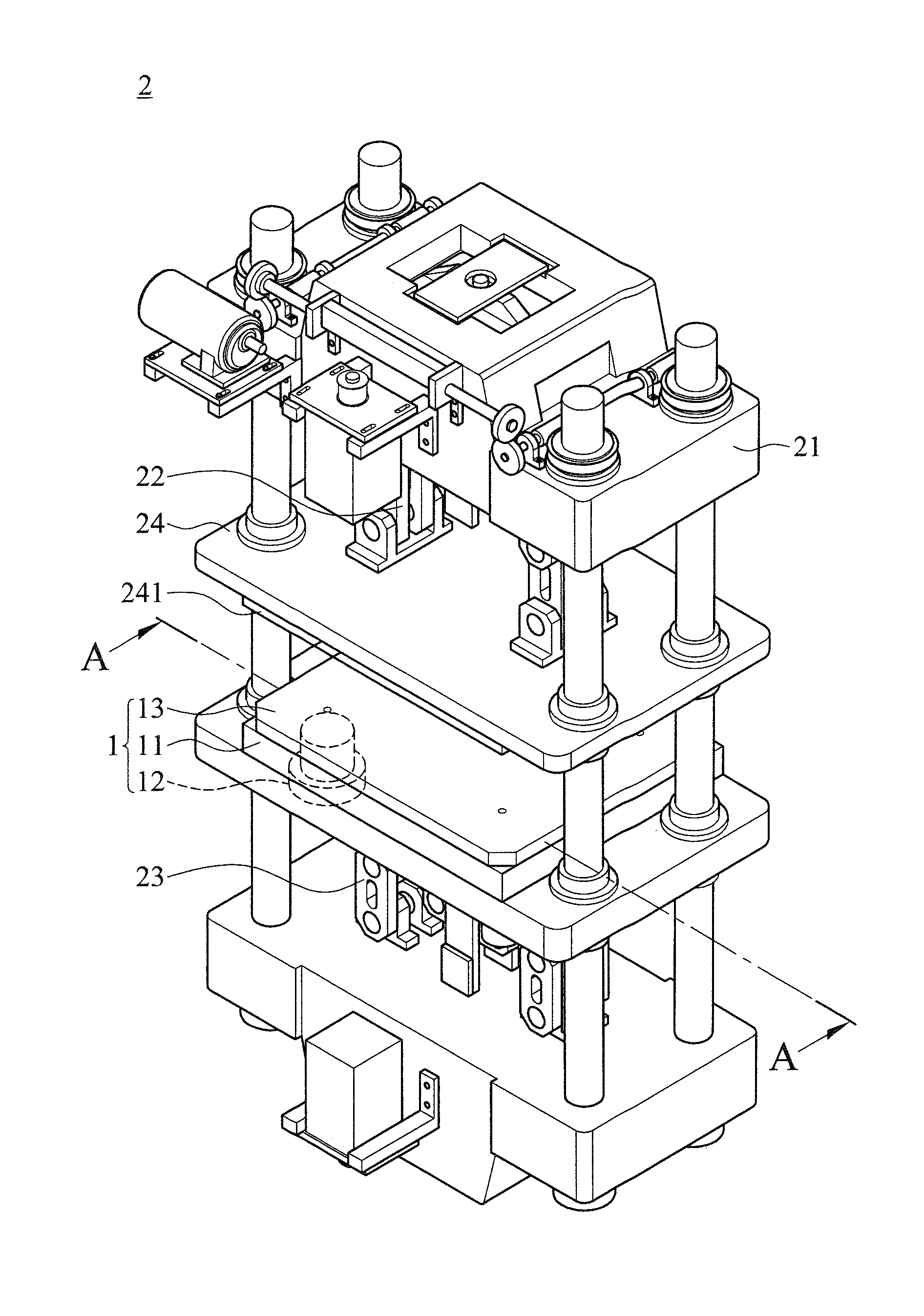
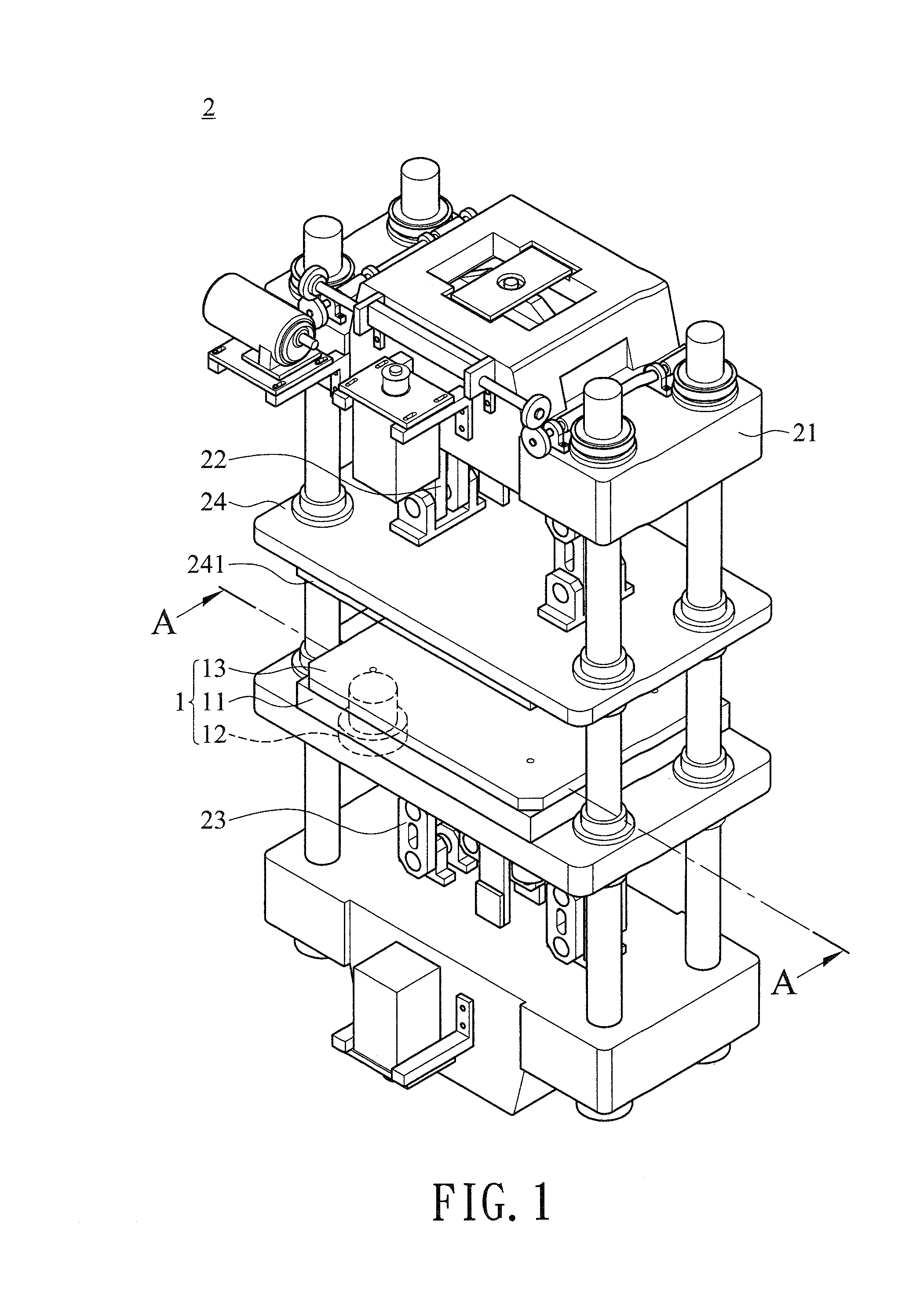
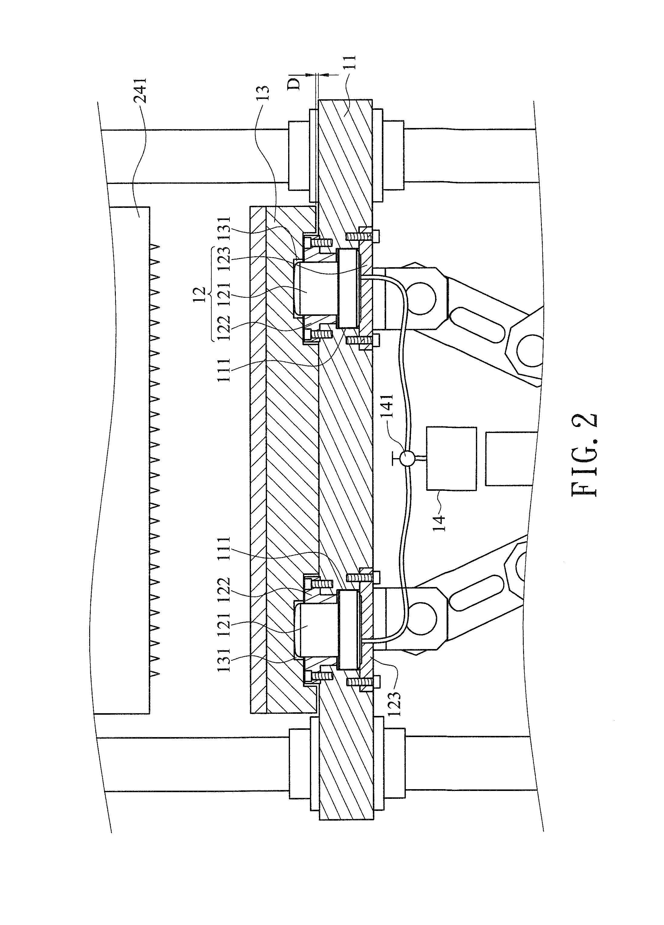
[0018]With reference to FIGS. 1, 2, and 3 to 5 for a schematic view, a partial blow-up view and schematic views of different operating statuses of a buffer assembly in accordance with a preferred embodiment of the present invention respectively, the buffer assembly 1 is applied to a vacuum molding and cutting machine 2, wherein the vacuum molding and cutting machine 2 is provided with an upper servo crane set 22 and a lower servo crane set 23 in a chassis 21. And the upper servo crane set 22 is coupled to a side of an upper mold base 24, and the upper mold base 24 includes a die cutting tool 241 installed thereon. The buffer assembly 1 comprises a lower mold base 11, four hydraulic elements 12 and a movable plate 13, and the lower servo crane set...


PUM

PropertyMeasurementUnit
cutting thicknessaaaaaaaaaa
distanceaaaaaaaaaa
diameteraaaaaaaaaa

Abstract

Disclosed is a buffer assembly of a vacuum molding and cutting machine, and the buffer assembly includes a lower mold base, at least four hydraulic elements and a movable plate. The lower mold base has at least four installing holes for installing the hydraulic elements respectively, and each hydraulic element includes a piston plunger for propping the movable plate to a predetermined distance. When the cutting thickness is 0.1 mm-0.5 mm of a sheet, the impact force can be absorbed effectively to maintain the parallelism for the cutting, so as to improve the cutting quality and extend the service life of a die cutting tool.

Description

CROSS-REFERENCE TO RELATED APPLICATIONS[0001]This non-provisional application claims priority under 35 U.S.C. §119(a) on Patent Application No(s). 101222758 filed in Taiwan, R.O.C. on Nov. 23, 2012, the entire contents of which are hereby incorporated by reference.BACKGROUND OF THE INVENTION[0002]1. Field of the Invention[0003]The present invention relates to the technical field of vacuum molding and cutting machines, and more particularly to a buffer assembly that buffers the impact and pressing forces produced by a cutting operation of a die cutting tool by a hydraulic element to ensure the parallelism of the cutting in order to cut a sheet uniformly and extend the service life of the die cutting tool.[0004]2. Description of the Related Art[0005]In recent years, pressure vacuum forming machines generally use a pair of servo cranks to drive an upper mold base and a lower mold base to improve the quality and efficiency of the forming process, and each servo crank is controlled and o...

Claims


Application Information

Patent Timeline
Patent Type & Authority Applications(United States)
IPC IPC(8): B29C51/26F16F15/023
CPCF16F15/023B29C51/26B26F1/40B30B15/007B30B15/062B26D5/12B29C51/38
Inventor WEI, CHIOU-SHENG
Owner CHENG MEI MACHINE
Why Eureka
Try Eureka