Wheel hub drive system

a hub drive and hub technology, applied in the direction of axially engaging brakes, vehicle sub-unit features, dynamo-electric machines, etc., to achieve the effect of improving the effectiveness of braking operation, improving control quality, and long communication tim

Active Publication Date: 2014-06-05
SCHAEFFLER TECH AG & CO KG
View PDF4 Cites 15 Cited by
  • Summary
  • Abstract
  • Description
  • Claims
  • Application Information

AI Technical Summary

Benefits of technology

[0027]In an advantageous embodiment, an electronic control unit is also arranged near the motor, ideally inside or partially inside the wheel rim, and this electronic control unit controls the interaction of the friction brake and the regenerative brake. In this manner, the effectiveness of the braking operation can be improved since the response times of the regenerative brake are markedly shorter because this brake does not have to make use of the primary communication via the CAN bus (controller area network).
[0028]The CAN bus makes information from each sensor available to all of the control devices, without permitting information differences between the control devices, as a result of which a longer communication time is tolerated. Consequently, due to the conventional CAN bus communication, the control signal to the friction brake is not accelerated in a special way. Thus, the regenerative brake can be activated at an earlier point in time than the friction brake, so that in the majority of cases, only a fraction of the requisite braking action has to be produced by the friction brake which is activated at a later point in time. For most braking operations, the electric motor has the necessary power to yield 100% of the necessary braking torque, but on average, 60% to 90% of the braking power is generated by the electric motor and only the remaining 10% to 40% is produced by the friction brake. As a result, the geometric size of the friction brake, especially its radial extension, can be smaller inside the electric motor, and more installation space will be available for the electric motor or for the converter.
[0029]Moreover, aside from the response times, the control quality can also be improved by the electronic control unit of the electric motor in that the electronic control unit as well as the friction brake receive the control signal via the CAN bus, but the electronic control unit of the electric motor can become active before, while and / or after the friction brake has become active.

Problems solved by technology

A problem in this context is that, for safety reasons, a friction brake also has to be provided and consequently, it has to be integrated into the rim space of the wheel together with the electric motor, in other words, especially with its stator and its rotor.

Method used


Image

  • Wheel hub drive system
  • Wheel hub drive system
  • Wheel hub drive system

Examples


Embodiment Construction

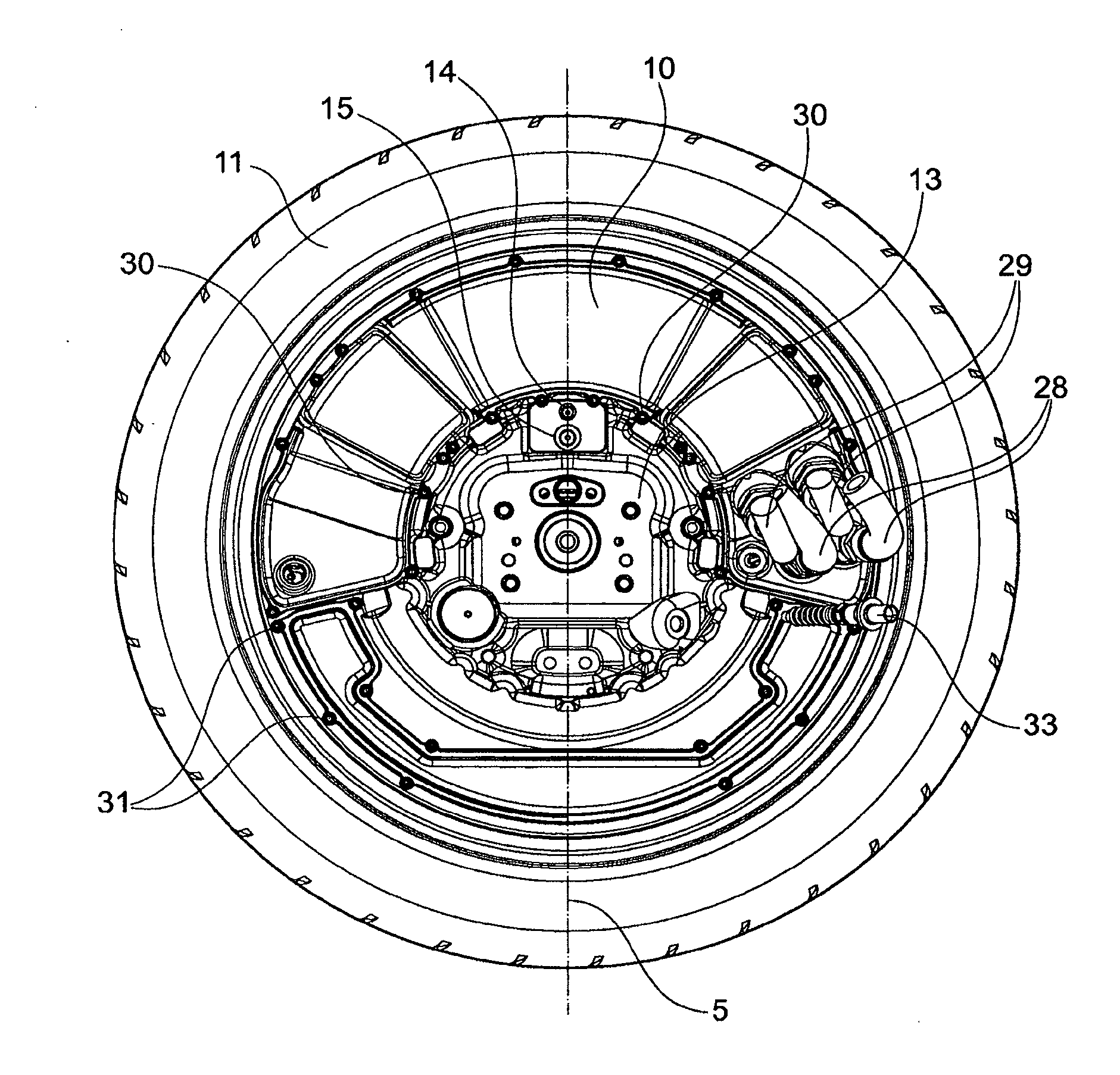
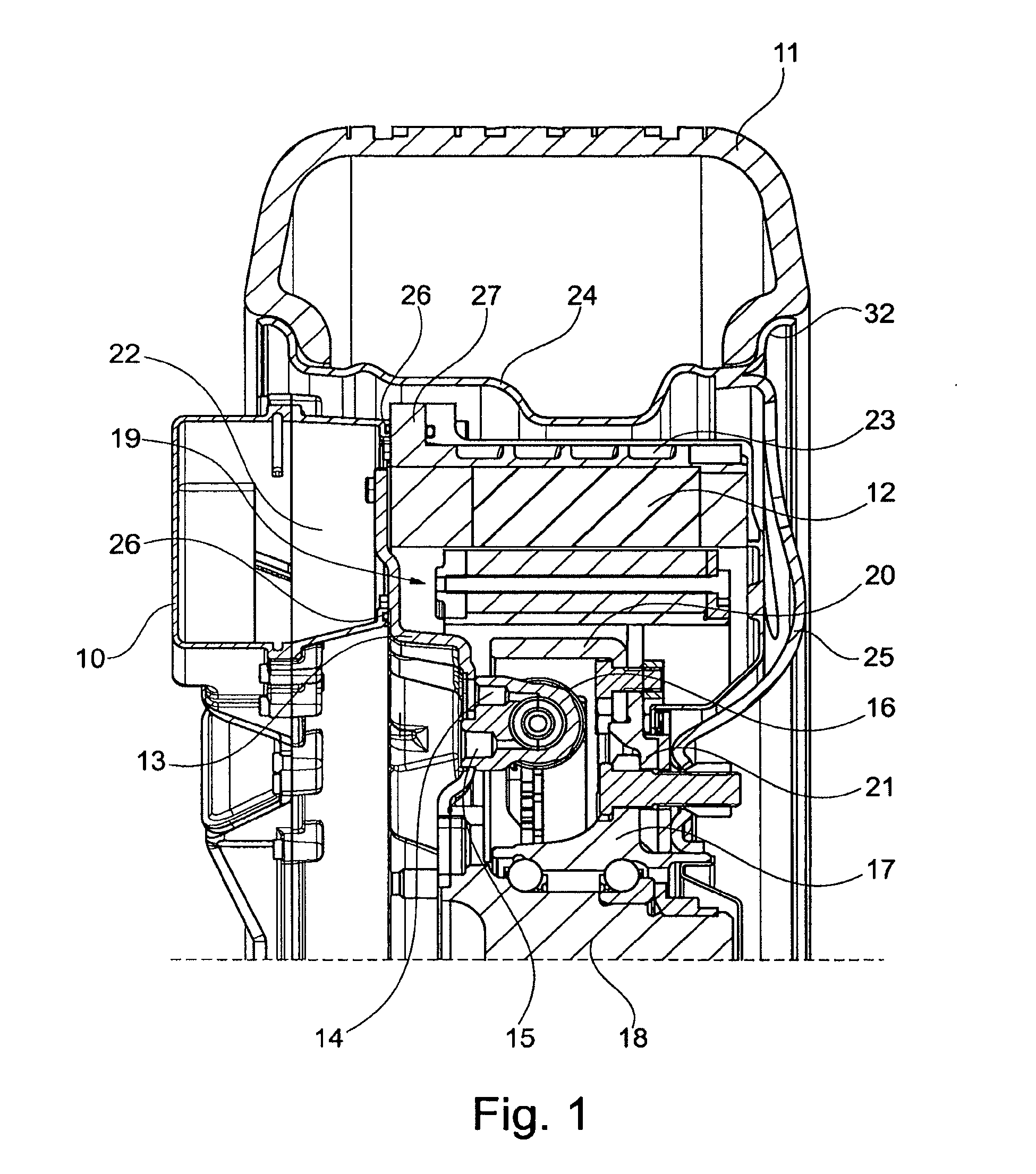
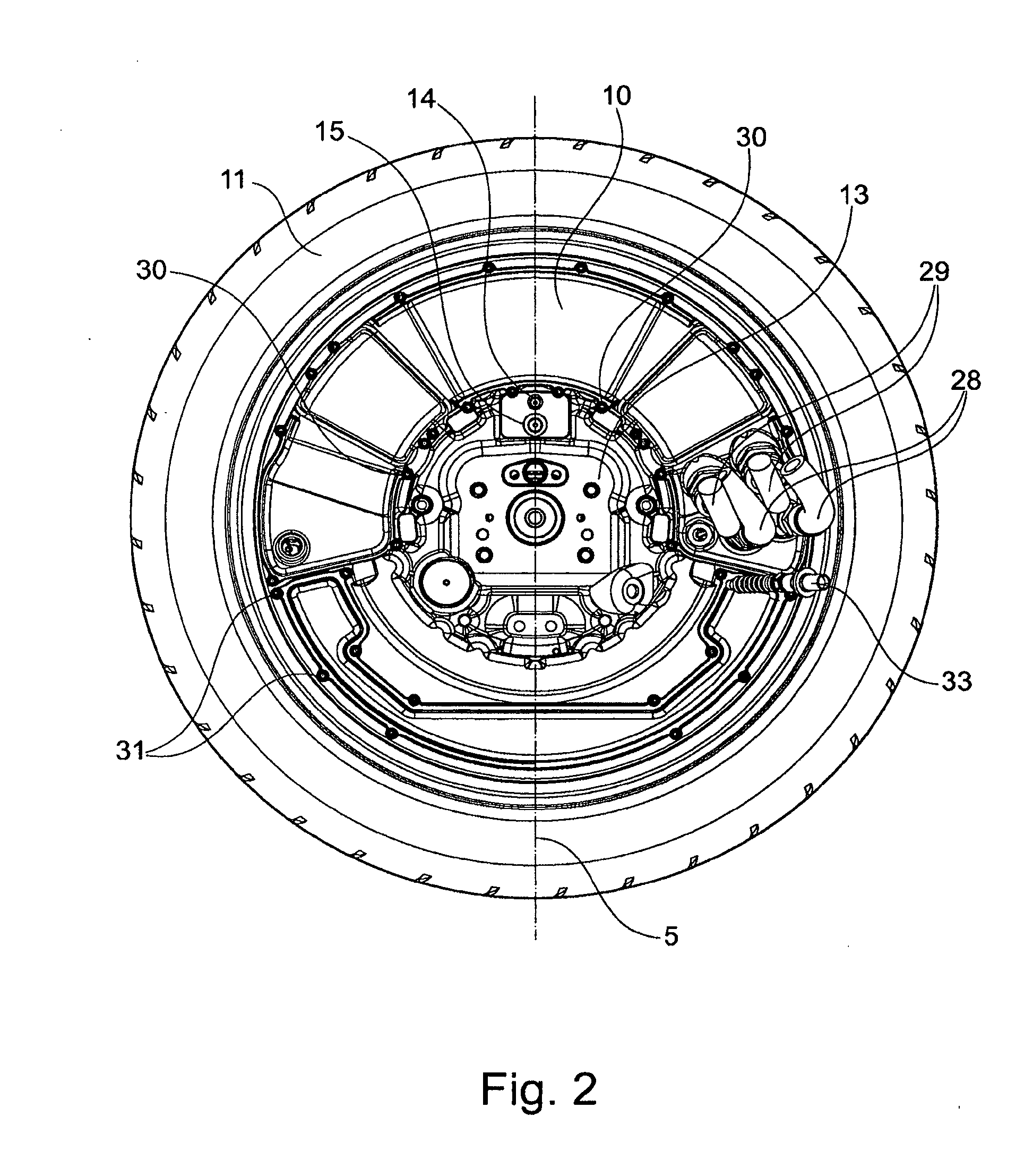
[0035]FIG. 1 shows a cut-away view along the drive axle of the wheel hub drive system arranged inside the wheel.

[0036]The wheel hub motor is arranged radially inside the wheel, whereby the tire 11 is mounted on the wheel rim 24. The wheel rim 24 is a so-called semi-full face wheel rim arrangement that provides a great deal of radial and axial motor space since the wheel rim front plate is made of steel and the almost disk-shaped wheel rim front plate is installed directly below the rim flange 32.

[0037]The stator includes a cooling element 27 with cooling channels 23 that are filled with a cooling fluid, especially water or a water-glycol mixture. Radially inside the cooling element 27, there is a coil element 12 that comprises a certain number of coils or their windings.

[0038]Since the rotor 19 is arranged radially inside the stator, the wheel hub motor is a so-called internal-rotor motor.

[0039]The stator 27, 12 is screwed onto a stator plate 13 which holds it in position so that th...


PUM


Abstract

A wheel hub drive system with an electric motor that can be arranged inside a wheel rim, whereby the electric motor is formed by rotor that is at least indirectly joined to a wheel hub and by means of a stationary stator that can be supplied with alternating current. With an eye towards obtaining more space for the vehicle occupants, it is proposed to arrange the converter with its entire power electronics unit on the stator so that the wheel hub drive system can be operated with direct current from the battery of the vehicle, or else no alternating current lines have to be laid in the vehicle. Consequently, the alternating current is generated by the converter that is arranged in a converter housing attached axially next to the stator.

Description

[0001]The invention relates to a wheel hub drive system with an electric motor that can be arranged inside a wheel rim, whereby the electric motor is formed by a rotor that is at least indirectly connected to a wheel hub and by means of a stationary stator that can be supplied with alternating current.BACKGROUND[0002]Wheel hub drive systems are direct drives with which the wheel is driven without transmission, for example, in the form of a gear. Instead, the rotational speed of the motor and of the driven wheel are the same at every point in time.[0003]Electric direct drives on the basis of permanently excited synchronous motors permit a very high efficiency so that the battery of the vehicle only has to store a fraction of the energy in comparison to the energy stored in the tank of a vehicle that has an internal combustion engine.[0004]In the past, directly driving electric motors were already integrated into the vehicle wheel, whereby the stator and the rotor of the electric moto...

Claims


Application Information

Patent Timeline
Patent Type & Authority Applications(United States)
IPC IPC(8): B60K7/00H02K11/00H02K7/00
CPCH02K7/14B60K2007/0038B60K2007/0092B60Y2400/61F16D49/00F16D55/00B60L15/007B60L2220/44H02K11/33B60L3/108B60L7/14B60L7/26B60L15/2009B60L15/2036B60L2220/14B60L2240/423B60L2270/147Y02T10/72B60L50/51B60K7/0007Y02T10/64Y02T10/70H02K7/006
Inventor VOGLER, TOBIASFISCHER, RAPHAELLAUGER, MARKSTIRNWEISS, DOROTHEE
Owner SCHAEFFLER TECH AG & CO KG
Why Eureka
Try Eureka