Backlight unit and display device

a backlight unit and display device technology, applied in the field of display manufacturing technology, can solve the problems of reducing the effective illumination area, and requiring a larger number of leds for the backlight unit, so as to improve the effective illumination area and improve the effect of light-emitting effect, the effect of expanding the application range of the backlight uni

Inactive Publication Date: 2014-06-05
BOE TECH GRP CO LTD +1
View PDF2 Cites 19 Cited by
  • Summary
  • Abstract
  • Description
  • Claims
  • Application Information

AI Technical Summary

Benefits of technology

[0017]The backlight unit according to the present invention can mix light uniformly in a short distance due to the fact that a direct-type side-light configuration (i.e., light emitted from the light source below the first reflector at a side of the light guide plate exits from the front of the light guide plate after being scattered by the light guide plate and being reflected by the second reflector at the back of the light guide plate) is employed. As compared with the existing direct-type backlight unit, the backlight unit according to the present invention can be ultra-thin (the thickness thereof is less than 5 mm); and the number of the LEDs (i.e., the light source) required is smaller. As compared with the existing side-edge backlight unit, the outer frame of the backlight unit according to the present is narrower (the width thereof is less than 5 mm), thereby increasing the effective illumination area relatively. The backlight unit according to the present invention can be circular, polygonal, or the like, having the advantage of diverse shapes, thereby expanding the application range of the backlight unit. The backlight unit also has advantages of good light-emitting effect, uniform emitted light, no stray light, etc.

Problems solved by technology

However, the direct-type backlight unit requires a larger number of LEDs (Light Emitting Diodes).
Thus, the direct-type backlight unit is generally thicker, and unable to be ultra-thin.
Thus, the outer frame of the side-edge backlight unit is much larger than that of the direct type backlight unit, relatively reducing the effective illumination area thereof.
Meanwhile, since the LED strips can only be formed in a linear and regular shape, it is difficult to form the side-edge backlight unit in a round shape or an irregular shape.

Method used


Image

  • Backlight unit and display device
  • Backlight unit and display device
  • Backlight unit and display device

Examples


embodiment 1

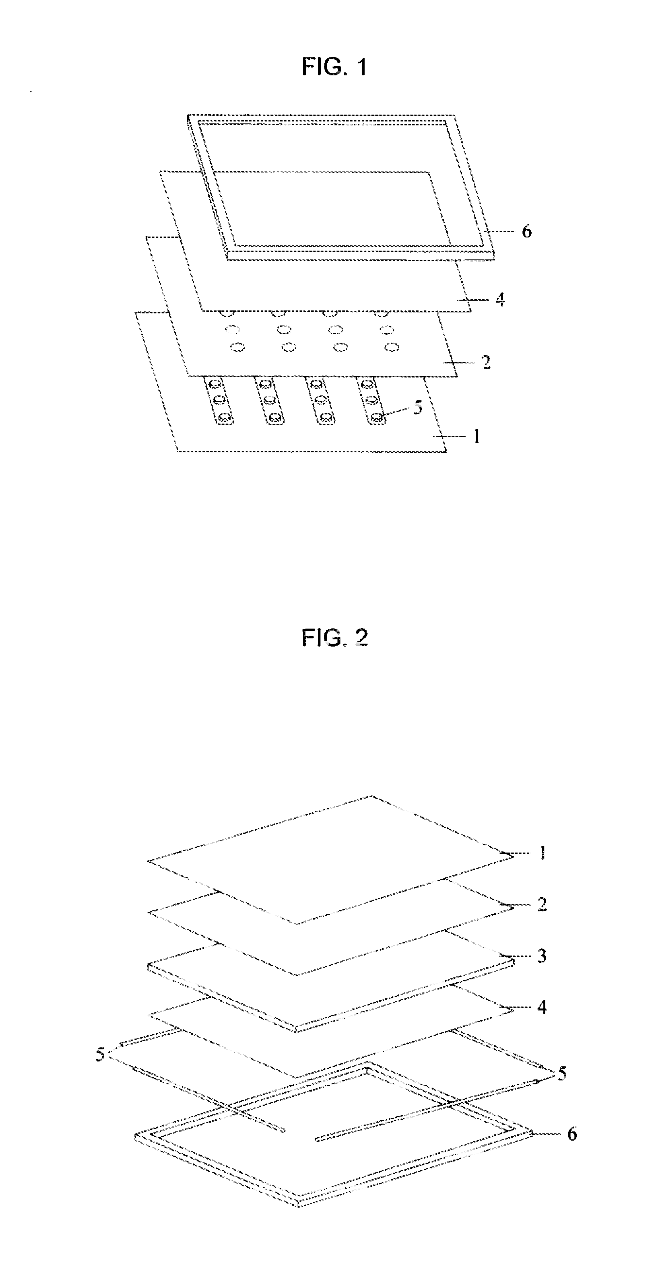
[0025]The present embodiment provides a backlight unit which includes a light guide plate, a light source, and a set of reflectors. The set of reflectors include a first reflector and a second reflector.

[0026]The first reflector is arranged at a side of the light guide plate. The second reflector is arranged at the back of the light guide plate. The light source is arranged below the first reflector. The first reflector is used to reflect light emitted from the light source into the light guide plate. Light is emitted from the front of the light guide plate after being scattered by the light guide plate and reflected by the second reflector.

[0027]The present embodiment further provides a display device including the backlight unit as described above.

[0028]It can be seen that light emitted from the light source in the backlight unit described in the present embodiment can uniformly mix in a short distance, since the light is emitted from the front of the light guide plate after being...

embodiment 2

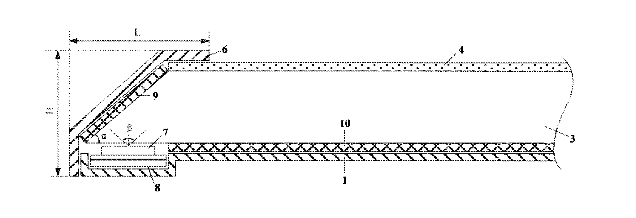
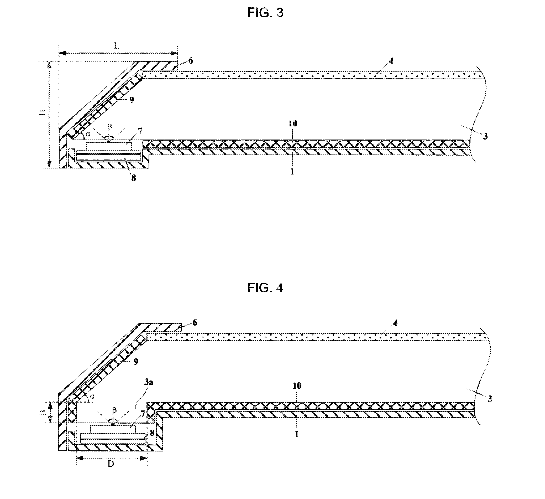
[0029]As shown in FIG. 3, the present embodiment provides a backlight unit, which includes a light guide plate 3, a light source 7, a PCB (printed circuit board) 8, an optical film 4, a first reflector 9, a second reflector 10, a backplane 1, and an outer frame 6. The optical film 4 includes a diffuser.

[0030]Wherein, the first reflector 9 is arranged at a side of the light guide plate 3, specifically may be arranged at any one or more of all sides of the light guide plate 3, and of course may be arranged at all sides around the light guide plate 3. The second reflector 10 is arranged at the back of the light guide plate 3. The light source 7 is arranged below the first reflector 9 and located on the PCB 8. It should be noted that, the light source 7 may be also arranged below the light guide plate 3, and the light-emitting surface of the light source 7 may be not in contact with the light guide plate 3 in order to prevent the light guide plate 3 being heated to melt due to heat gene...

embodiment 3

[0041]As shown in FIG. 4, the backlight unit according to the present embodiment is different from that according to Embodiment 2 in that:

[0042]The light guide plate 3 of the backlight unit further includes a bulge 3a which is arranged at a bottom edge of the light guide plate 3. The bulge 3a extends into a recessed portion of the backplane 1. The light source 7 is arranged below the bulge 3a (the light-emitting surface of the light source 7 is not in contact with the bulge 3a either), to avoid light emitted from a portion of the light source 7 which is close to the first reflector 9 being unable to be transmitted to the optical film 4 and being lost, due to limitation of the light-emitting angle of the light source. Thus, the utilization ratio of the reflected light of light emitted from the light source after being reflected by the first reflector 9 is increased.

[0043]Preferably, the relationship among the thickness B of the bulge 3a, the width D of the bulge 3a, and the light-emi...


PUM


Abstract

The present invention provides a backlight unit including a light source and a light guide plate, wherein the backlight unit further includes a set of reflectors, the set of reflectors includes a first reflector and a second reflector, the first reflector is arranged at a side of the light guide plate, the second reflector is arranged at the back of the light guide plate, the light source is arranged below the first reflector, the first reflector is used for reflecting light emitted from the light source into the light guide plate, and light exits from the front of the light guide plate after being scattered by the light guide plate and being reflected by the second reflector. Correspondingly, a display device including the backlight unit is provided. The backlight unit has advantages of small thickness, increased effective illumination area, and various shapes.

Description

FIELD OF THE INVENTION[0001]The present invention relates to the field of display manufacturing technology, in particular, relates to a backlight unit, and a display device including the backlight unit.BACKGROUND OF THE INVENTION[0002]Nowadays, a liquid crystal display (LCD) has been dominant in the panel display market for its advantages of small size, low power consumption, low radiation, and the like. In order to display an image on a screen of the LCD, it is necessary to configure a backlight unit (BLU) for a display panel. This is because the liquid crystals in the LCD can not emit light by themselves, and the liquid crystals just regulate the light.[0003]In general, the BLUs may be categorized into side-edge backlight units and direct-type backlight units according to the distribution positions of light sources in the BLUs. The light source in the side-edge backlight unit is positioned at a side of the display panel, and the light source in the direct-type backlight unit is po...

Claims


Application Information

Patent Timeline
Patent Type & Authority Applications(United States)
IPC IPC(8): F21V8/00
CPCG02B6/0031G02B6/009G02B6/0055G02B6/0051
Inventor ZHAO, YANGZHOU, ZHENDONG
Owner BOE TECH GRP CO LTD
Why Eureka
Try Eureka