Mobile robot system and method of controlling the same

a robot and mobile technology, applied in the field of mobile robots, can solve the problems of frequent charge unnecessary waste of high power for transmitting the signal, user may be dissatisfied with the life span of the battery, etc., and achieve the effect of reducing energy consumption of the beacon battery, low power consumption, and high power consumption

Active Publication Date: 2014-06-05
SAMSUNG ELECTRONICS CO LTD
View PDF20 Cites 14 Cited by
  • Summary
  • Abstract
  • Description
  • Claims
  • Application Information

AI Technical Summary

Benefits of technology

The patent text describes a mobile robot system that improves the energy efficiency of a battery by restricting the traveling region of the mobile robot to only when it detects a signal transmitted from the mobile robot with low power consumption. The method of controlling the system involves transmitting a low-power signal while the mobile robot travels in a specific region, receiving the signal at a beacon equipped with a remote controller reception module, and responding with a signal to the mobile robot to prevent collision. This approach reduces energy consumption of the beacon battery while restricting the movement of the mobile robot. Additionally, the system includes a lighthouse function to guide the movement of the mobile robot to another room after completing cleaning of one room. This innovation satisfies various user requirements when multiple rooms need to be cleaned.

Problems solved by technology

However, since the beacon continuously transmits the signal even when the mobile robot is not in a signal arrival range of the beacon, high power for transmitting the signal is unnecessarily wasted.
Due to the unnecessary power consumption, a battery of the beacon is frequently charged and thus is frequently replaced with a new battery.
Thus, a user may be dissatisfied with the life span of the battery.
In addition, the Field-of-View (FOV) of the remote control reception module is restricted by a directivity receiver.

Method used


Image

  • Mobile robot system and method of controlling the same
  • Mobile robot system and method of controlling the same
  • Mobile robot system and method of controlling the same

Examples


Embodiment Construction

[0046]Reference will now be made in detail to the embodiments, examples of which are illustrated in the accompanying drawings, wherein like reference numerals refer to the like elements throughout. The embodiments are described below to explain the present invention by referring to the figures.

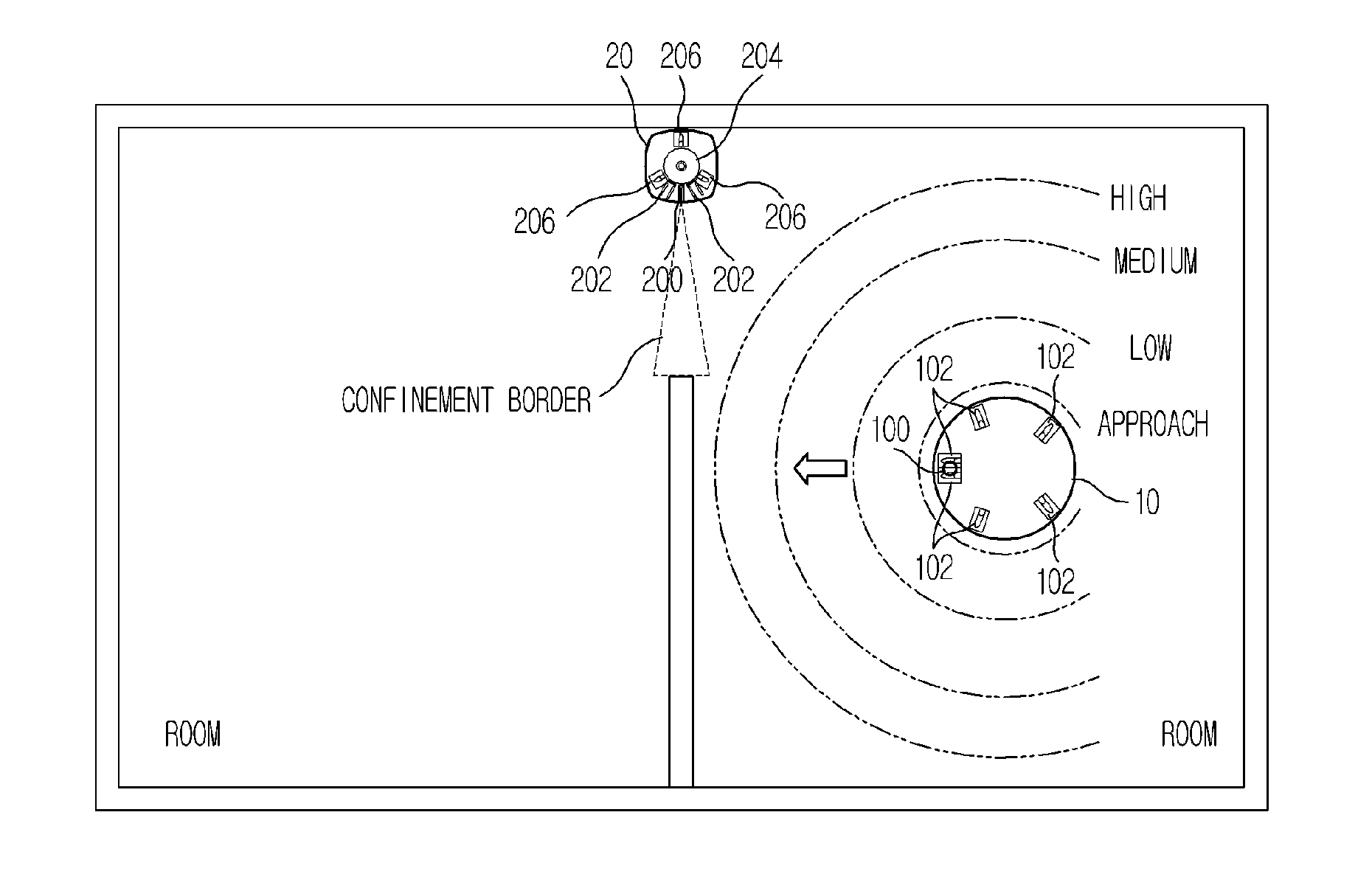
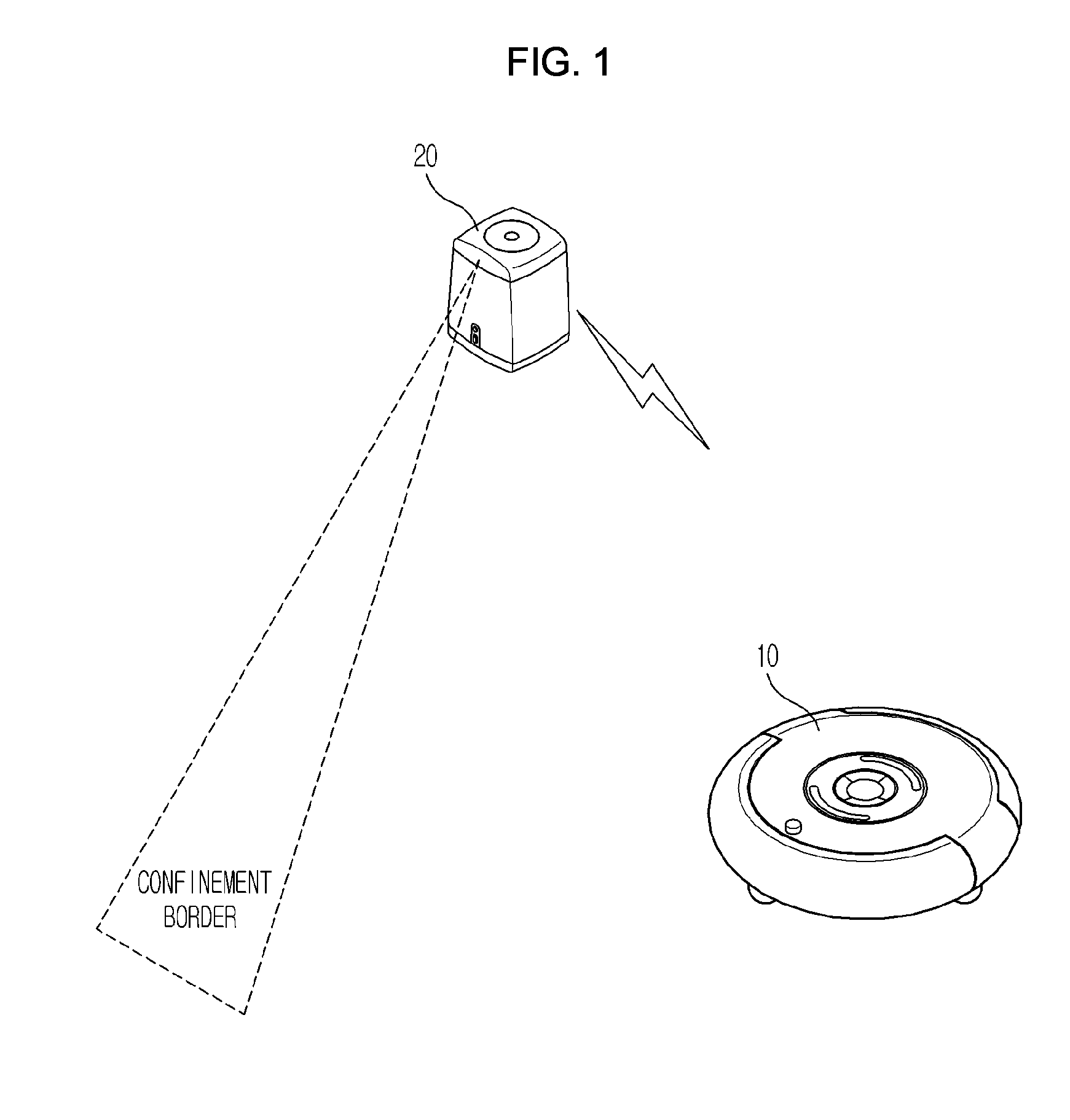
[0047]FIG. 1 is a view showing the overall configuration of a mobile robot system according to an embodiment. The mobile robot system includes a mobile robot 10 to perform a cleaning operation while autonomously traveling in a predetermined region and to transmit an infrared ray (IR) signal in packet units, and a beacon 20 separated from the mobile robot 10 to receive the signal transmitted from the mobile robot 10.

[0048]The beacon 20 is movably mounted at a border (for example, a corner between a living room and a kitchen, a door between rooms, or the like) of a traveling region in order to restrict a traveling region of the mobile robot 10. The beacon 20 detects a signal transmitted from the...


PUM


Abstract

A method of controlling a mobile robot system is provided. The method includes at a mobile robot, transmitting a signal while traveling in a traveling region, at a beacon, receiving the signal transmitted from the mobile robot over 360 degrees and determining whether the mobile robot has approached the beacon, at the beacon, transmitting a response signal to the mobile robot if the mobile robot has approached the beacon, and at the mobile robot, performing avoidance navigation to prevent collision with the beacon when the mobile robot receives the response signal of the beacon.

Description

CROSS-REFERENCE TO RELATED APPLICATIONS[0001]This application is a divisional application of pending U.S. application Ser. No. 12 / 662,942 filed May 12, 2010, which claims the priority benefit of Korean Patent Application No. 10-2009-0042784, filed on May 15, 2009 in the Korean Intellectual Property Office, and Korean Patent Application No. 10-2009-101527, filed on Oct. 26, 2009 in the Korean Intellectual Property Office, the disclosures of which are incorporated herein by reference.BACKGROUND[0002]1. Field[0003]Embodiments relate to a mobile robot system to restrict a traveling region of a robot and to guide the robot to another region, and a method of controlling the same.[0004]2. Description of the Related Art[0005]Generally, a mobile robot is a device to perform an operation while autonomously traveling in a traveling region without user control. A robot cleaner which is a mobile robot sucks foreign materials such as dust from a floor while autonomously traveling in a predetermin...

Claims


Application Information

Patent Timeline
Patent Type & Authority Applications(United States)
IPC IPC(8): B25J9/16B25J5/00B25J9/00B25J11/00
CPCB25J9/1676B25J9/0003B25J5/00B25J11/0085G05D1/0234
Inventor HONG, JUN PYOYOO, KYUNG HWANJUNG, JAE YOUNGJOO, JAE MANKIM, DONG WONCHUNG, WOO RAMJANG, HWI CHAN
Owner SAMSUNG ELECTRONICS CO LTD
Why Eureka
Try Eureka