Method of manufacturing annular molding

a technology of annular molding and manufacturing method, which is applied in the direction of manufacturing tools, metal rolling arrangements, transportation and packaging, etc., can solve the problems of inability to achieve mechanical strength sufficiently, and inability to achieve desired uniform and fine structure, etc., to ensure the uniform grain size and ensure the effect of grain size uniformity and stability of rolling

Active Publication Date: 2014-06-12
MITSUBISHI MATERIALS CORP
View PDF3 Cites 18 Cited by
  • Summary
  • Abstract
  • Description
  • Claims
  • Application Information

AI Technical Summary

Benefits of technology

[0028]According to the fifth aspect, since the difference between the grain sizes of the equivalent positions in the circumferential direction of the annular material may be suppressed to be in a range of ±1.5 as an ASTM grain size number difference, the annular material obtained by making the annular intermediate sufficiently ensures the uniformity of grain sizes in the circumferential direction. Specifically, the ring rolling is local processing but is different from general partial forging. It is known that since the ring rolling processes continuity, the axisymmetry of the structure after rolling is high and the deviation of the material property in the circumferential direction in the annular material is reduced. By setting the ratio T / H in the annular intermediate before the ring rolling to be in the above-described range, the axisymmetry of the shape (roundness) and the micro structure of the made annular material may be further increased.
[0029]That is, since the ratio T / H is in the range of 0.6 to 2.3, stability of rolling that is necessary to provide uniformity is caused. Specifically, in a region in which the T / H is less than 0.6, the contact area between the two rolls (a main roll and a mandrel roll) that perform rolling and the material is increased, the effect of heat removal is relatively increased, and thus it is difficult to obtain the uniformity in the circumferential direction. On the other hand, as the T / H is increased, buckling is more likely to occur. Specifically, in a region in which the T / H is higher than 2.3, the tendency is strengthened, and thus it is difficult to obtain the uniformity in the circumferential direction.
[0030]According to the method of manufacturing an annular material according to the present invention, facility costs and manufacturing costs may be reduced while ensuring uniformity of the micro structure and sufficiently increasing mechanical strength.

Problems solved by technology

However, in case of making through a making method according to the related art in which high reduction ratios are exerted in the ring rolling process, even though a structure including fine equiaxed grains is obtained as a result of the ring rolling, the generation of strong anisotropy of strength property caused by exerting a high strain cannot be avoided.
When such anisotropy occurs in the structure of the annular material, it is difficult to sufficiently obtain mechanical strength.
On the other hand, when strain to be exerted is limited in order to avoid the generation of anisotropy, a desired uniform and fine structure may not be obtained.
Therefore, when ring rolling is to be applied, there is a need to perform complex processes including preform forging, ring rolling, and finish forging.

Method used


Image

  • Method of manufacturing annular molding
  • Method of manufacturing annular molding
  • Method of manufacturing annular molding

Examples


example 1

Making of Specimen

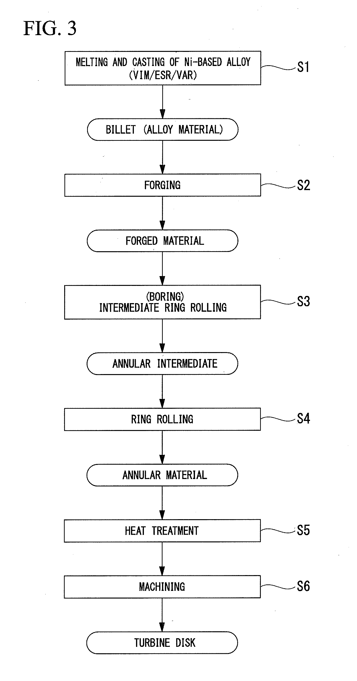
[0088]First, the melted metal of the Ni-based alloy Alloy 718 was made. Specifically, melting raw materials were prepared to achieve the composition range of the Ni-based alloy Alloy 718 described in the above-described embodiment. The melted metal was subjected to triple melting processes. Specifically, vacuum induction melting (VIM), electroslag remelting (ESR), and vacuum arc remelting (VAR) were performed thereon, thereby making a columnar billet having a diameter of φ254 mm.

[0089]Next, the forging process was performed on the billet, thereby making the discoid forged material. As the forging, the hot forging in which the billet was heated to a temperature of 1000° C. was performed twice. The first hot forging was performed so that the absolute value εθ1 of the strain in the circumferential direction of the forged material was 0.3, the absolute value εh of the strain in the height direction of the forged material was 0.6, and the ratio εh / εθ1 between the absolu...

example 2

Making of Specimen

[0097]As in Example 1, after making a billet through three melting processes, the forging process was performed on the billet, thereby making the discoid forged material.

[0098]Next, the through-hole was formed in the center portion of the forged material by the water cutter, thereby making the annular intermediate 20. The annular intermediate 20 was made so that the ratio T / H of the thickness T and the height H was T / H=1.4.

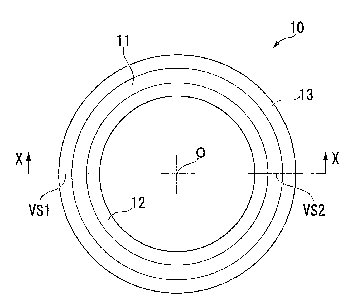
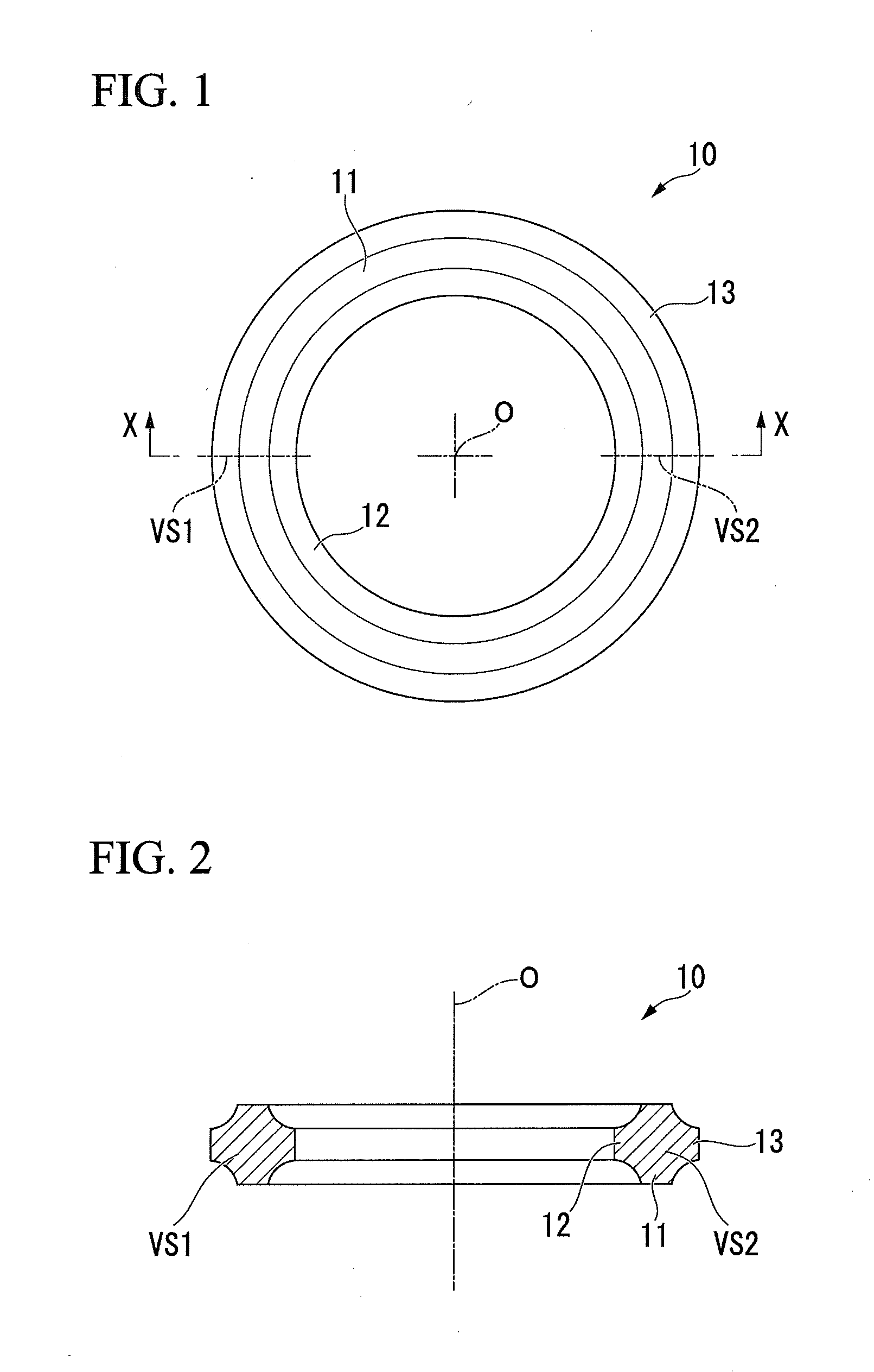
[0099]Next, the ring rolling was performed on the annular intermediate 20. As the ring rolling, the hot rolling in which the annular intermediate 20 was heated to a temperature of 1000° C. was performed once. Due to the hot rolling, 0.3 of the absolute value εθ2 of the strain in the circumferential direction of the annular material 10 was exerted. The annular material 10 obtained by subjecting the annular intermediate 20 to the ring rolling was made to have an outside diameter of about φ680 mm, an inside diameter of about $20 mm (that is, the thi...

example 3

Making of Specimen

[0101]As in Example 1, after making a billet through three melting processes, the forging process was performed on the billet, thereby making the discoid forged material. As the forging work, the hot forging in which the billet was heated to a temperature of 1000° C. was performed twice. Each of both the first and second hot forging processes was performed so that the absolute value εθ1 of the strain in the circumferential direction of the forged material was 0.3, the absolute value εh of the strain in the height direction of the forged material was 0.6, and the ratio εh / εθ1 between the absolute values of the strains was 2.

[0102]Next, the through-hole was formed in the center portion of the forged material by the water cutter, thereby making the annular intermediate 20. The annular intermediate 20 was made so that the ratio T / H of the thickness T and the height H was T / H=0.4.

[0103]Next, the ring rolling was performed on the annular intermediate 20. As the ring roll...


PUM

PropertyMeasurementUnit
temperatureaaaaaaaaaa
diameteraaaaaaaaaa
temperatureaaaaaaaaaa

Abstract

A method of manufacturing an annular material includes: a forging process of making a discoid forged material by forging an alloy material; and a ring rolling process of making an annular material by performing ring rolling on an annular intermediate made by forming a through-hole in the forged material. In the forging process, hot forging which achieves an absolute value εθ1 of a strain in a circumferential direction of the forged material that is greater than or equal to 0.3, an absolute value εh of a strain in a height direction of the forged material that is greater than or equal to 0.3, and a ratio εh/εθ1 between the absolute values of the strains that is in a range of 0.4 to 2.5 is performed at least two or more times.

Description

BACKGROUND OF THE INVENTION[0001]1. Field of the Invention[0002]The present invention relates to a method of manufacturing an annular material represented by a turbine disk of an engine for an aircraft. Particularly, the present invention relates to a manufacturing method related to an annular material having excellent uniformity.[0003]2. Background Art[0004]Hitherto, an annular material made of an alloy such as a Ni-based alloy, a Fe-based alloy, or a Co-based alloy is known. For example, an annular material made of a Ni-based alloy having excellent high-temperature strength is used in a turbine disk of an engine for an aircraft, and the turbine disk as a product is manufactured by machining the annular material.[0005]A plurality of turbine blades is arranged in the outer circumference portion of the turbine disk along the circumferential direction. In the engine for an aircraft, as high-temperature and high-pressure combustion gas generated in the engine flows from the front side ...

Claims


Application Information

Patent Timeline
Patent Type & Authority Applications(United States)
IPC IPC(8): B23P15/02
CPCB21H1/06B21J1/025B21J1/04B21J5/02B21K1/28B23P15/006
Inventor TAKIZAWA, HIDEOISHIWARI, YUJIKIKUCHI, HIROAKIOHSONE, JUN
Owner MITSUBISHI MATERIALS CORP
Why Eureka
Try Eureka