Gasket and cylinder head gasket

Active Publication Date: 2014-06-12
ISHIKAWA GASKET CO LTD
10 Cites 4 Cited by

AI-Extracted Technical Summary

Problems solved by technology

As a result, both the cylinder block and the cylinder head have a low rigidity.
As a result, a stress at a periphery of the water jacket or at a periphery of the cylinder bore increases locally, and there is a problem that the cylinder bore or a cylinder liner inserted into the cylinder bore is distorted or deformed.
Accordingly, a distortion or a deformation of the cylinder bore or the cylinder liner tends to occur.
If the cylinder bore or the cylinder liner is distorted or deformed, and is no longer capable of maintaining a circular shape, an unnecessary resistance is gener...

Method used

[0047]If the fastening-stress reduction beads 18 formed linearly are disposed on the head-bolt axis line L1, they can be easily manufactured, and have a great effect reducing the fastening stress as well. Incidentally, in the embodiment, four bolt holes 6 are provided relative to one cylinder bore 4, so that the head-bolt axis line L1 connecting the center O of the cylinder-bore hole 12 and the center P of the bolt hole 14 exactly becomes a diagonal line of a polygonal shape which has the center P of each bolt hole 14 enclosing one cylinder-bore hole 12 at the top. The fastening-stress reduction beads 18 are provided on the diagonal line thereof so as to reduce the fastening stress generated between all the bolt holes 14 and the cylinder-bore holes 12 provided around the cylinder-bore holes 12.
[0048]On the other hand, the fastening-stress reduction beads 18 can not block the surface pressure of the cylinder-bore hole bead...

Benefits of technology

[0023]According to the structure, the fastening-stress reduction portion is provided within the range of the fastening-stress concentration area, so that in a case wherein the cylinder block and the cylinder head are fastened by a high head-bolt axial force, the fastening-stress reduction portion, provided between a head bolt (the fixture) and a cylinder bore (the sealing subject hole), becomes a resistance not allowing the cylinder block to be distorted. Thereby, the distortion or the deformation of the cylinder bore or a cylinder liner due to the fastening stress can be controlled.
[0024]In a case of the cylinder block having a lightweight and a low rigidity, when the cylinder block is fastened by the high head-bolt axial force, since a thickness of an upper surface is thin, there acts a force pulling up an inner circumferential surface of the cylinder block, and a stress at a periphery of a water jacket or at a periphery of the cylinder bore increases locally. Especially, in a case of a closed-deck-type cylinder block, the head bolt and the cylinder bore are connected so as to increase the stress of the relevant portion.
[0025]In the pre...

Abstract

A gasket includes at least one metal plate; a fixture hole formed in the at least one metal plate, for inserting a fixture therein; a sealing subject hole formed in the at least one metal plate; and a fastening-stress concentration area located on the at least one metal plate between the fixture hole and the sealing subject hole where a fastening stress concentrates when the two members are fastened by the fixture. A fastening-stress reduction portion is formed only on the fastening-stress concentration area to reduce the fastening stress when the two members are fastened.

Application Domain

Engine sealsSealing arrangements for engines +1

Technology Topic

Head gasketStress concentration +2

Image

  • Gasket and cylinder head gasket
  • Gasket and cylinder head gasket
  • Gasket and cylinder head gasket

Examples

  • Experimental program(1)

Example

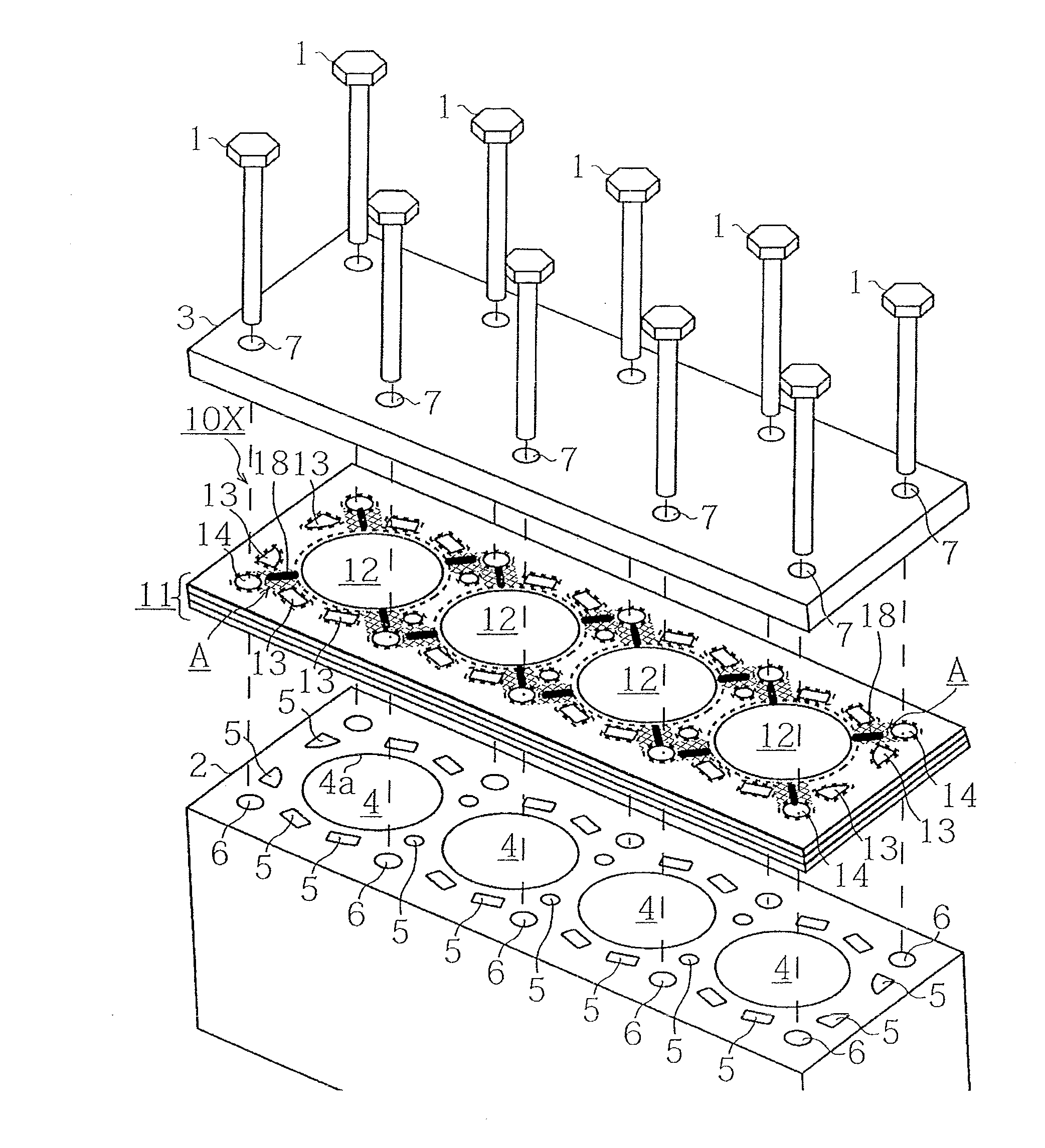
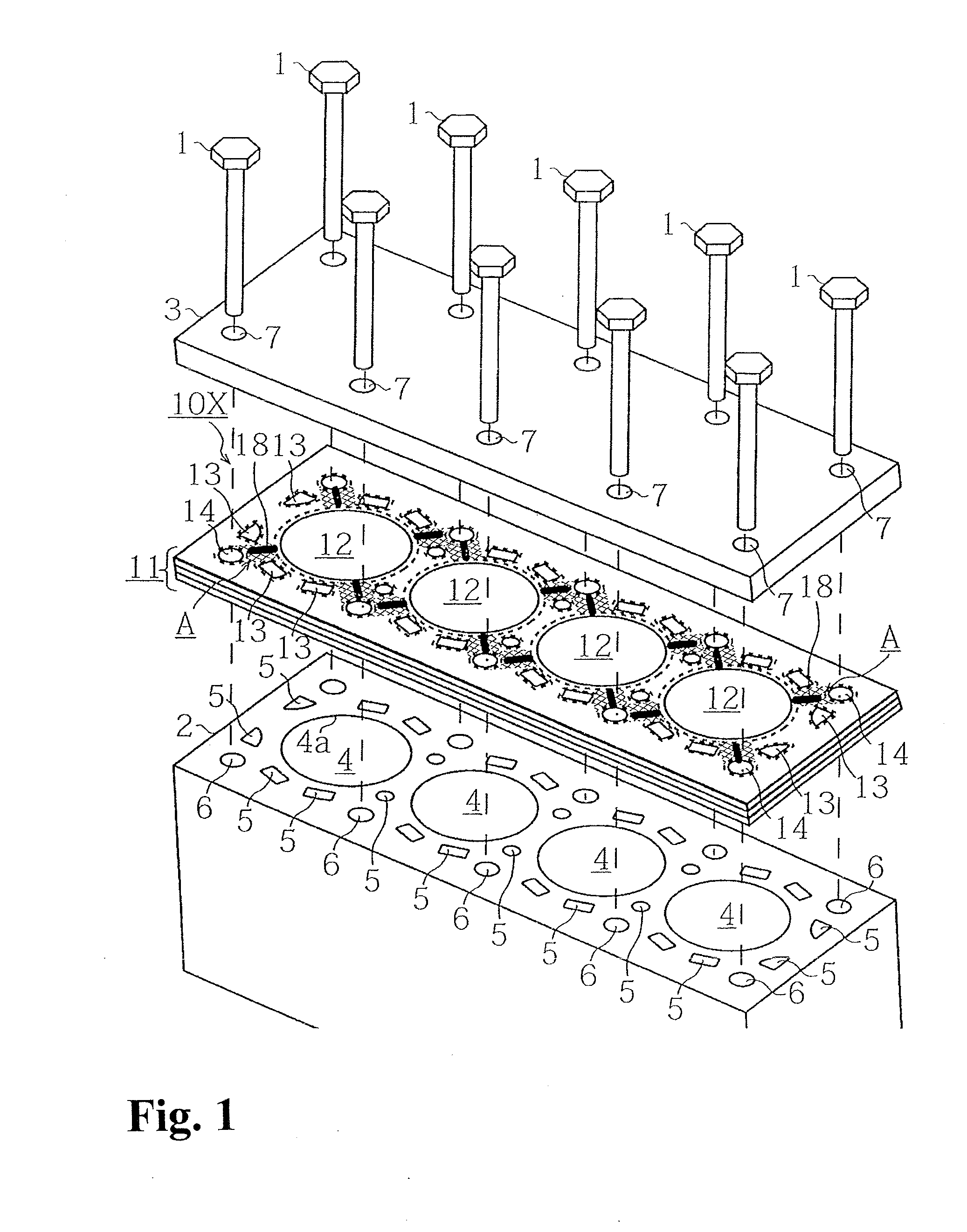
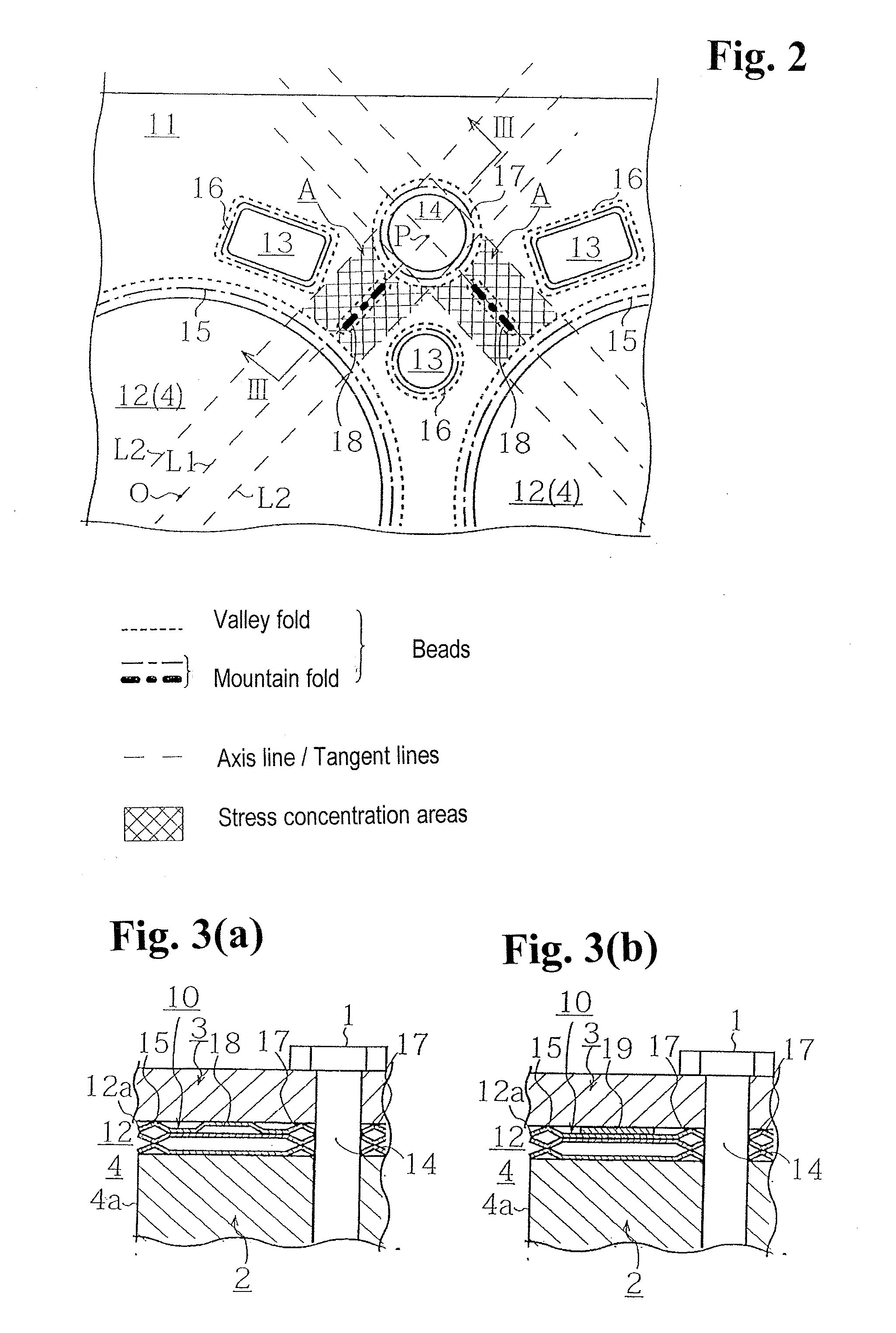
[0035]Hereinafter, a gasket and a cylinder head gasket of an embodiment according to the present invention will be explained with reference to drawings. Incidentally, in FIGS. 1 to 7, sizes are changed for the sake of explanation of a configuration, and sizes of a dimension of a cylinder-bore hole, a water hole, a thickness of beads, a shape, and the like do not necessarily correspond to a ratio of actual manufactured ones.
[0036]Also, as the embodiment, FIGS. 1 to 4(d) explain the cylinder head gasket used for an in-line four-cylinder engine as an example. However, as for an engine to which the present invention can be applied, the number of cylinders and an array thereof are not limited. Also, in the present invention, especially a closed-deck type wherein a water jacket portion is not all open exerts the most effect. However, the present invention can be applied to an open-deck type as well.
[0037]Moreover, for the embodiment, FIGS. 5(a) and 5(b) explain an intake-and-exhaust-system gasket as an example. The term intake-and-exhaust-system gasket here indicates a gasket which is provided in a joint line between a pipe arrangement and a pipe arrangement of a muffler, a manifold, and the like.
[0038]A cylinder head gasket 10 of the embodiment according to the present invention will be explained with reference to FIGS. 1 to 4(d). The cylinder head gasket 10 is formed in a configuration of a conventional cylinder head gasket 10X shown in FIG. 6. As shown in FIG. 1, when a cylinder block 2 and a cylinder head 3 (two members) are fastened by head bolts (fixtures) 1, in fastening-stress concentration areas A wherein a fastening stress concentrates between bolt holes (fixture holes) 14, through which the head bolts 1 pass, and cylinder-bore holes (sealing subject holes) 12, there are provided fastening-stress reduction beads (fastening-stress reduction portions) 18 extending only in the fastening-stress concentration areas A.
[0039]Here, the fastening-stress concentration areas A will be explained. As shown in FIG. 2, the fastening-stress concentration areas A are areas wherein the fastening stress concentrates when the cylinder block 2 and the cylinder head 3 are fastened by the head bolts 1. Specifically, the fastening-stress concentration areas A are the areas between the cylinder-bore holes 12 and the bolt holes 14, and are the areas enclosed by two bolt-hole tangent lines L2 of the bolt hole 14 parallel to a head-bolt axis line L1 connecting a center (the center of a cylinder bore 4) O of the cylinder-bore hole 12, and a center P of the bolt hole 14; an outer circumferential edge (in a case of the embodiment, indicating cylinder-bore hole beads 15) of the cylinder-bore hole 12; and an outer circumferential edge (in the case of the embodiment, indicating bolt hole beads 17) of the bolt hole 14.
[0040]Generally, around each cylinder bore 4 provided in the cylinder block 2, there is provided a plurality of bolt holes 6. In the embodiment, there are provided four bolt holes 6 relative to one cylinder bore 4. Therefore, each cylinder-bore hole 12 is enclosed by four fastening-stress concentration areas A, and when the cylinder block 2 and the cylinder head 3 are fastened by the head bolts 1, stresses at a periphery of water jackets 5 and at a periphery of the cylinder bores 4 increase locally in the respective four fastening-stress concentration areas A.
[0041]In the present invention, in order to control a distortion or a deformation of each cylinder bore 4, there are provided the fastening-stress reduction beads 18 in all respective fastening-stress concentration areas A (in the embodiment, since there are four fastening-stress concentration areas A relative to one cylinder bore, there are sixteen fastening-stress concentration areas A).
[0042]The fastening-stress reduction beads 18 are the beads except for seal beads such as the cylinder-bore hole beads 15; water hole beads 16; the bolt hole beads 17; and the like, and are the beads extending only inside the fastening-stress concentration areas A. In the fastening-stress reduction beads 18, a cross-sectional shape thereof or a shape in a plan view are not specially limited. Also, the fastening-stress reduction beads 18 do not contribute to the cylinder-bore hole beads 15 provided around the cylinder-bore hole 12; the water hole beads 16 provided around the water hole 13; and the bolt hole beads 17 provided around the bolt hole 14, and are configured not to block a surface pressure of each of the beads 15 to 17.
[0043]In the embodiment, as shown in FIG. 3(a), as the fastening-stress reduction portions, there are provided the fastening-stress reduction beads 18 formed in a convex type toward the cylinder head 3, and the fastening stress of the fastening-stress concentration areas A is reduced. However, in place of the fastening-stress reduction beads 18, for example, as shown in FIG. 3(b), on a substrate 11 formed by a plurality of metal plates, there may be provided a fastening-stress reduction shim 19 which can press against the cylinder head 3 when the cylinder block 2 and the cylinder head 3 are fastened by the head bolts 1.
[0044]Also, the cross-sectional shape, and the shape in the plan view of the fastening-stress reduction beads 18, the number of the fastening-stress reduction beads 18 provided in one fastening-stress concentration area A, and the like are not specially limited. For example, as fastening-stress reduction beads 21 in FIG. 4(a), the fastening-stress reduction beads 21 may be provided by displacing the fastening-stress reduction beads 21 from the head-bolt axis line L1. In that case, relative to the head-bolt axis line L1, the fastening-stress reduction beads 21 are disposed to have a predetermined angle, or may be disposed not to intersect with the head-bolt axis line L1. Also, as fastening-stress reduction beads 22 in FIG. 4(b), the fastening-stress reduction beads 22 may be formed in a polygonal shape, and may be formed in various shapes such as a circular shape, an oval shape, and the like besides the polygonal shape.
[0045]Additionally, as fastening-stress reduction beads 23 in FIG. 4(c), the fastening-stress reduction beads 23 may not be arranged linearly in the plan view, and may be meandered in a W shape, an S shape, or the like. Moreover, as fastening-stress reduction beads 24 and 25 shown in FIG. 4(d), a plurality of the fastening-stress reduction beads 18 may be provided in one fastening-stress concentration area A.
[0046]As mentioned above, the fastening-stress reduction portions can be formed in the beads or shims having various shapes, and be disposed in the fastening-stress concentration area A. However, preferably, for example, as shown in FIG. 1, each fastening-stress reduction beads 18 may be arranged radially relative to the cylinder-bore hole 12. More preferably, as shown in FIG. 2, the fastening-stress reduction beads 18, whose cross-sectional shape is an arbitrary shape and which are formed in a linear shape in the plan view, may be disposed on the head-bolt axis line L1 connecting the center O of the cylinder-bore hole 12 and the center P of the bolt hole 14.
[0047]If the fastening-stress reduction beads 18 formed linearly are disposed on the head-bolt axis line L1, they can be easily manufactured, and have a great effect reducing the fastening stress as well. Incidentally, in the embodiment, four bolt holes 6 are provided relative to one cylinder bore 4, so that the head-bolt axis line L1 connecting the center O of the cylinder-bore hole 12 and the center P of the bolt hole 14 exactly becomes a diagonal line of a polygonal shape which has the center P of each bolt hole 14 enclosing one cylinder-bore hole 12 at the top. The fastening-stress reduction beads 18 are provided on the diagonal line thereof so as to reduce the fastening stress generated between all the bolt holes 14 and the cylinder-bore holes 12 provided around the cylinder-bore holes 12.
[0048]On the other hand, the fastening-stress reduction beads 18 can not block the surface pressure of the cylinder-bore hole beads 15, the water hole beads 16, and the bolt hole beads 17, so that, for example, as shown in FIG. 4(a), if the fastening-stress reduction beads 21 are provided by displacing the fastening-stress reduction beads 21 from the head-bolt axis line L1, a clearance between the cylinder-bore hole beads 15, the water hole beads 16, and the bolt hole beads 17 can be obtained so as to be capable of preventing the surface pressure from being blocked.
[0049]According to the aforementioned configuration, in the fastening-stress concentration areas A of the cylinder head gasket 10 clamped between the cylinder block 2 and the cylinder head 3, there is provided the fastening-stress reduction beads 18 to become a resistance when the cylinder block 2 and the cylinder head 3 are fastened by the head bolts 1, and the fastening stress when the cylinder block 2 and the cylinder head 3 are fastened by the head bolts 1 is reduced so as to be capable of controlling the distortion or the deformation of the cylinder bore 4, or a cylinder liner which is not shown in the figures due to the fastening stress.
[0050]Especially, as explained in the aforementioned embodiment, the fastening stress of the closed-deck-type cylinder block 2 is reduced, and the distortion, the deformation, or the like of the cylinder bore 4 or the cylinder liner can be controlled, so that the shape of a cylinder is maintained, and an unnecessary resistance is not allowed to be generated in the cylinder bore 4 and a piston (not shown in the figures) inside the cylinder so as to be capable of improving fuel consumption.
[0051]Incidentally, a material of the metal plates forming the substrate 11 of the cylinder head gasket 10, and the number of the metal plates are not limited, and for example, the metal plates forming the substrate 11 may be configured by one sheet of the metal plate instead of a plural number.
[0052]Next, an intake-and-exhaust-system gasket 30 of the embodiment according to the present invention will be explained with reference to FIGS. 5(a) and 5(b). As shown in FIG. 5(a), the intake-and-exhaust-system gasket 30 comprises an exhaust-gas hole 32 and bolt holes 33 in a substrate 31 formed by one sheet or a plurality of the metal plates, and exhaust-gas hole beads 34 and bolt hole beads are respectively provided in circumferential edge portions thereof.
[0053]Then, in fastening-stress concentration areas B that are enclosed by two bolt-hole tangent lines L4 of the bolt hole 33 parallel to a head-bolt axis line L3 connecting a center Q of the exhaust-gas hole 32 and a center R of the bolt hole 33; an outer circumferential edge (in the case of the embodiment, indicating the exhaust-gas hole beads 34) of the exhaust-gas hole 32; and an outer circumferential edge (in the case of the embodiment, indicating the bolt hole beads 35) of the bolt hole 33, fastening-stress reduction beads 36 are formed.
[0054]The fastening-stress reduction beads 36 provided in the fastening-stress concentration areas B are formed in the shape explained in the fastening-stress reduction beads 18 provided in the fastening-stress concentration areas A of the first embodiment, and the like. The fastening-stress reduction beads 36 do not block the surface pressure of the exhaust-gas hole beads 34, and the bolt hole beads 35 so as to be capable of reducing the fastening stress in the fastening-stress concentration areas B.
[0055]In the embodiment, there have been illustrated an example, as shown in FIG. 5(a), wherein three bolt holes 33 are provided, and the substrate 31 is formed in a triangle shape, or an example, as shown in FIG. 5(b), wherein two bolt holes 33 are provided, and the substrate 31 is formed in a rhombus shape. However, in the present invention, the shape of the substrate 31 or the number of the bolt holes 33 are not limited.
[0056]Incidentally, as for the embodiment of the present invention, there have been explained the cylinder head gasket 10 and the intake-and-exhaust-system gasket 30 as an example. However, the present invention can be applied provided that the gasket is a gasket clamped between two members fastened by a fixture such as a bolt and the like. For example, the present invention can be applied to a transmission, a gasket for a clutch cover, and the like.
[0057]The gasket of the present invention reduces the fastening stress generated when the two members are fastened by the fixture, and can control the distortion, the deformation, and the like due to the fastening stress so as to be capable of being used for sealing a closed-deck-type engine, wherein the cylinder bore is going to be distorted due to the fastening stress especially when the two members are fastened.
[0058]The disclosure of Japanese Patent Application No. 2012-268199, filed on Dec. 7, 2012, is incorporated in the application.
[0059]While the invention has been explained with reference to the specific embodiments of the invention, the explanation is illustrative and the invention is limited only by the appended claims.

PUM

no PUM

Description & Claims & Application Information

We can also present the details of the Description, Claims and Application information to help users get a comprehensive understanding of the technical details of the patent, such as background art, summary of invention, brief description of drawings, description of embodiments, and other original content. On the other hand, users can also determine the specific scope of protection of the technology through the list of claims; as well as understand the changes in the life cycle of the technology with the presentation of the patent timeline. Login to view more.

Similar technology patents

Structure for a terminal in an electric connector

InactiveUS20110130050A1maximum toleranceincrease stress
Owner:TYCO ELECTRONICS (SHANGHAI) CO LTD

Flexible cover plate and flexible display panel

PendingCN113628537Aincrease stressreduce cracks
Owner:SHENZHEN ROYOLE TECH CO LTD

Semiconductor structure and forming method thereof

PendingCN112289746AImprove formation qualityincrease stress
Owner:SEMICON MFG INT (SHANGHAI) CORP +1

Turn-back type fusing load-reducing force-bearing structure at fan end of low-pressure rotor of engine

PendingCN114856728Aincrease stressoptimal structure
Owner:INST OF ENGINEERING THERMOPHYSICS - CHINESE ACAD OF SCI

Classification and recommendation of technical efficacy words

  • low rigidity
  • increase stress

Damper device

ActiveUS20160356340A1low rigidityrigidity be lower
Owner:AISIN AW CO LTD

System for forming holes in metal sheet

InactiveUS20090098404A1calculation time be increaselow rigidity
Owner:HONDA MOTOR CO LTD

Instrument panel

InactiveUS20110187145A1low rigidityeasily bent
Owner:SUZUKI MOTOR CO LTD

Pellicle

ActiveUS20140106265A1low rigidity
Owner:SHIN ETSU CHEM CO LTD

Sodium bicarbonate production from nahcolite

InactiveUS6699447B1decrease it compression strengthincrease stress
Owner:AMERICAN SODA

Method of controlling a power factor correction converter and related closed-loop control system

ActiveUS20150155776A1reduce switch lossincrease stress
Owner:STMICROELECTRONICS INT NV

Method for manufacturing high-tension film and strain silicon metal oxide semiconductor transistor

InactiveCN1967784Aincrease stress
Owner:UNITED MICROELECTRONICS CORP

Structure for a terminal in an electric connector

InactiveUS20110130050A1maximum toleranceincrease stress
Owner:TYCO ELECTRONICS (SHANGHAI) CO LTD
Why Eureka
Try Eureka