
Augmented field of view imaging system

a technology of imaging system and augmented field, which is applied in the field of imaging system, can solve the problems of poor ergonomics, lack of tactile feedback, and difficulty in visualizing surgical targets

Inactive Publication Date: 2014-06-12
THE JOHN HOPKINS UNIV SCHOOL OF MEDICINE
View PDF12 Cites 71 Cited by
  • Summary
  • Abstract
  • Description
  • Claims
  • Application Information

AI Technical Summary

Benefits of technology

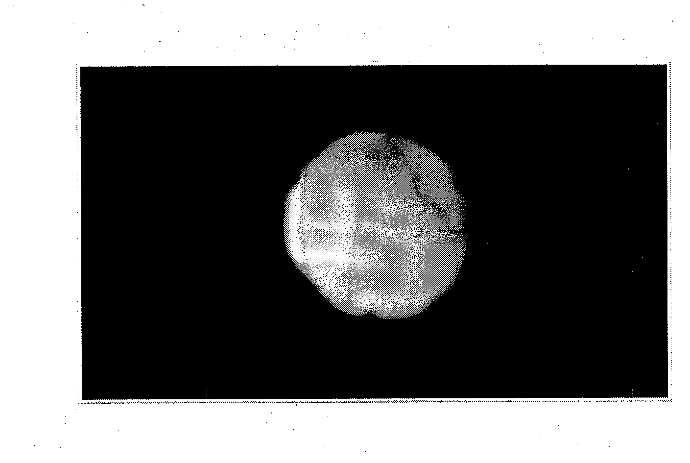
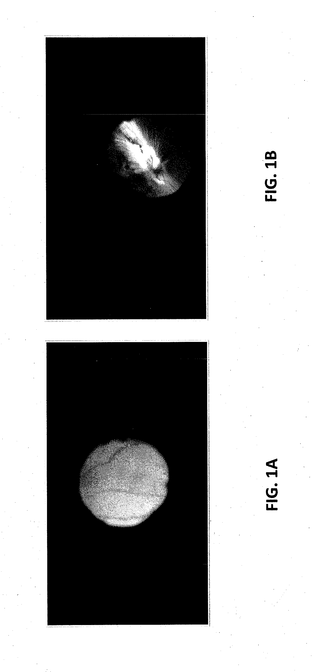
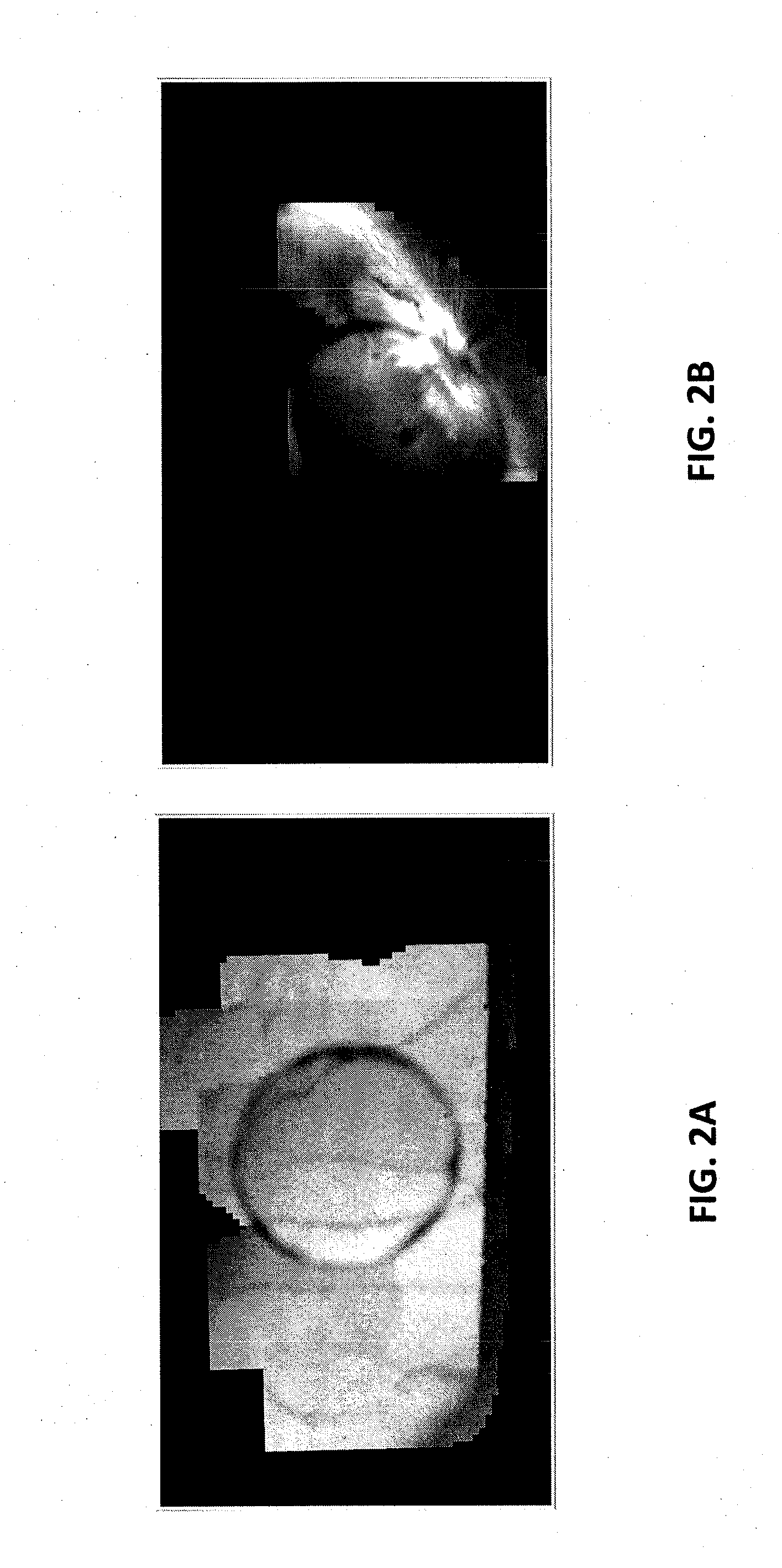
The present invention describes an augmented field of view imaging system that uses a microscope and an image sensor system to capture images of an object as it is being moved. The system includes an image processing and data storage system that tracks multiple fields of view in real-time and creates a mosaic image by combining the live field of view from the microscope with the mosaic image. This results in an augmented field of view image that provides a wider and more complete view of the object being examined. The technical effects of this invention include improved image quality, improved field of view, and improved visual content analysis.

Problems solved by technology

Difficulties related to this type of surgery arise from several factors such as the difficult visualization of surgical targets, poor ergonomics, lack of tactile feedback, complex anatomy, and high accuracy requirements.
Specifically regarding intra-operative visualization, surgeons face limitations in field and clarity of view, depth perception and illumination which hinder their ability to identify and localize surgical targets.
These limitations result in long operating times and risks of surgical error.
Although several solutions have been proposed in the field of minimally invasive surgery and functional imaging [6, 7], retinal surgery imposes additional challenges such as highly variable illumination (the illumination source is manually manipulated inside the eye), partial and full occlusions, focus blur due to narrow depth of field and distortions caused by the flexible eye lens.
Although the systems proposed in [4, 5] suggest potential improvements in surgical guidance, they lack robustness to such disturbances.

Method used


Image

  • Augmented field of view imaging system
  • Augmented field of view imaging system
  • Augmented field of view imaging system

Examples


example 1

REFERENCES FOR EXAMPLE 1

[0105]1. Mitchell, B., Koo, J., Iordachita, I., Kazanzides, P., Kapoor, A., Handa, J., Taylor, R., Hager, G.: Development and application of a new steady-hand manipulator for retinal surgery. In: ICRA, Rome, Italy (2007) 623-629[0106]2. Bergeles, C., Kummer, M. P., Kratochvil, B. E., Framme, C., Nelson, B. J.: Steerable intravitreal inserts for drug delivery: in vitro and ex vivo mobility experiments. In: MICCAI. (LNCS), Toronto, Canada, Springer (2011) 33-40[0107]3. Balicki, M., Han, J., Iordachita, I., Gehlbach, P., Handa, J., Taylor, R., Kang, J.: Single fiber optical coherence tomography microsurgical instruments for computer and robot-assisted retinal surgery. In: MICCAI. Volume 5761 of (LNCS)., London, UK, Springer (2009) 108-115[0108]4. Fleming, I., Voros, S., Vagvolgyi, B., Pezzementi, Z., Handa, J., Taylor, R., Hager, G.: Intraoperative visualization of anatomical targets in retinal surgery. In: IEEE Workshop on Applications of Computer Vision (WACV'...

example 2

REFERENCES FOR EXAMPLE 2


PUM


Abstract

An augmented field of view imaging system includes a microscope, an image sensor system arranged to receive images of a plurality of fields of view from the microscope as the microscope is moved across an object being viewed and to provide corresponding image signals, an image processing and data storage system configured to communicate with the image sensor system to receive the image signals and to provide augmented image signals, and at least one of an image injection system or an image display system configured to communicate with the image processing and data storage system to receive the augmented image signals and display an augmented field of view image. The image processing and data storage system is configured to track the plurality of fields of view in real time and register the plurality of fields of view to calculate a mosaic image. The augmented image signals from the image processing and data storage system provide the augmented image such that a live field of view from the microscope is composited with the mosaic image.

Description

CROSS-REFERENCE OF RELATED APPLICATION[0001]This invention was made with Government support of Grant No. 1 R01 EB 007969, awarded by the Department of Health and Human Services, The National Institutes of Health (NIH). The U.S. Government has certain rights in this invention.BACKGROUND[0002]1. Field of Invention[0003]The field of the currently claimed embodiments of this invention relates to imaging systems, and more particularly to augmented field of view imaging systems.[0004]2. Discussion of Related Art[0005]Retinal surgery is considered one of the most demanding types of surgical intervention. Difficulties related to this type of surgery arise from several factors such as the difficult visualization of surgical targets, poor ergonomics, lack of tactile feedback, complex anatomy, and high accuracy requirements. Specifically regarding intra-operative visualization, surgeons face limitations in field and clarity of view, depth perception and illumination which hinder their ability ...

Claims


Application Information

Patent Timeline
IPC IPC(8): G06T19/00
CPCG02B21/008G06T11/00G06T3/4038G06T2207/10056G06T2207/10101G06T2207/20221G06T2207/30041A61F9/008A61B2090/3735G06T7/337
Inventor TAYLOR, RUSSELL H.VAGVOLGYI, BALAZS PETERHAGER, GREGORY D.ROGERIO, RICHA
Owner THE JOHN HOPKINS UNIV SCHOOL OF MEDICINE
Features
  • Generate Ideas
  • Intellectual Property
  • Life Sciences
  • Materials
  • Tech Scout
  • Unparalleled Data Quality
  • Higher Quality Content
  • 60% Fewer Hallucinations
Learn More