Eureka AIR delivers breakthrough ideas for toughest innovation challenges, trusted by R&D personnel around the world.

Sanding disk alignment tool

a technology of sanding disk and tool, which is applied in the field of hand-held power tools, can solve the problems of affecting the effectiveness and lifespan of the abrasive disk, affecting the operator of the tool, and damaging the work surfa

Inactive Publication Date: 2014-06-12
TURNER CHRIS R
View PDF4 Cites 3 Cited by
  • Summary
  • Abstract
  • Description
  • Claims
  • Application Information

AI Technical Summary

Benefits of technology

The present invention is a tool designed for repeatedly applying sanding disks to a sander's platen with proper alignment between the collection holes of the platen and the corresponding holes in the sanding disk. The tool allows for easy and secure attachment of the sanding disk, enabling use in any orientation and is portable and easily kept at the ready for use in a jobsite or remote location.

Problems solved by technology

Inhaling airborne sanding dust is unhealthy for the operator of the tool.
Dust that remains on the work surface may damage the work surface and negatively impacts the effectiveness and lifespan of the abrasive disk.
Alignment of the disc on the platen is typically done manually by the operator and it difficult to get exactly right even with experience.
New disks are often applied and removed several times before the operator is satisfied with the alignment of the holes, wasting time and rarely resulting in perfect alignment.
However, in use it is critical to maintain the support plate and disk in a parallel orientation to the surface of the platen so the entire disk engages the surface at the same time or proper alignment will not be achieved.
This orientation is difficult to maintain unless the device is advanced into the sander from below such that gravity maintains the disk in contract with the support plate.
Consequently, insertion of the dowels into the holes of the platen is made more difficult because the holes are obscured from the operator's view on the underside of the sander.

Method used


Image

  • Sanding disk alignment tool
  • Sanding disk alignment tool
  • Sanding disk alignment tool

Examples


embodiment 100

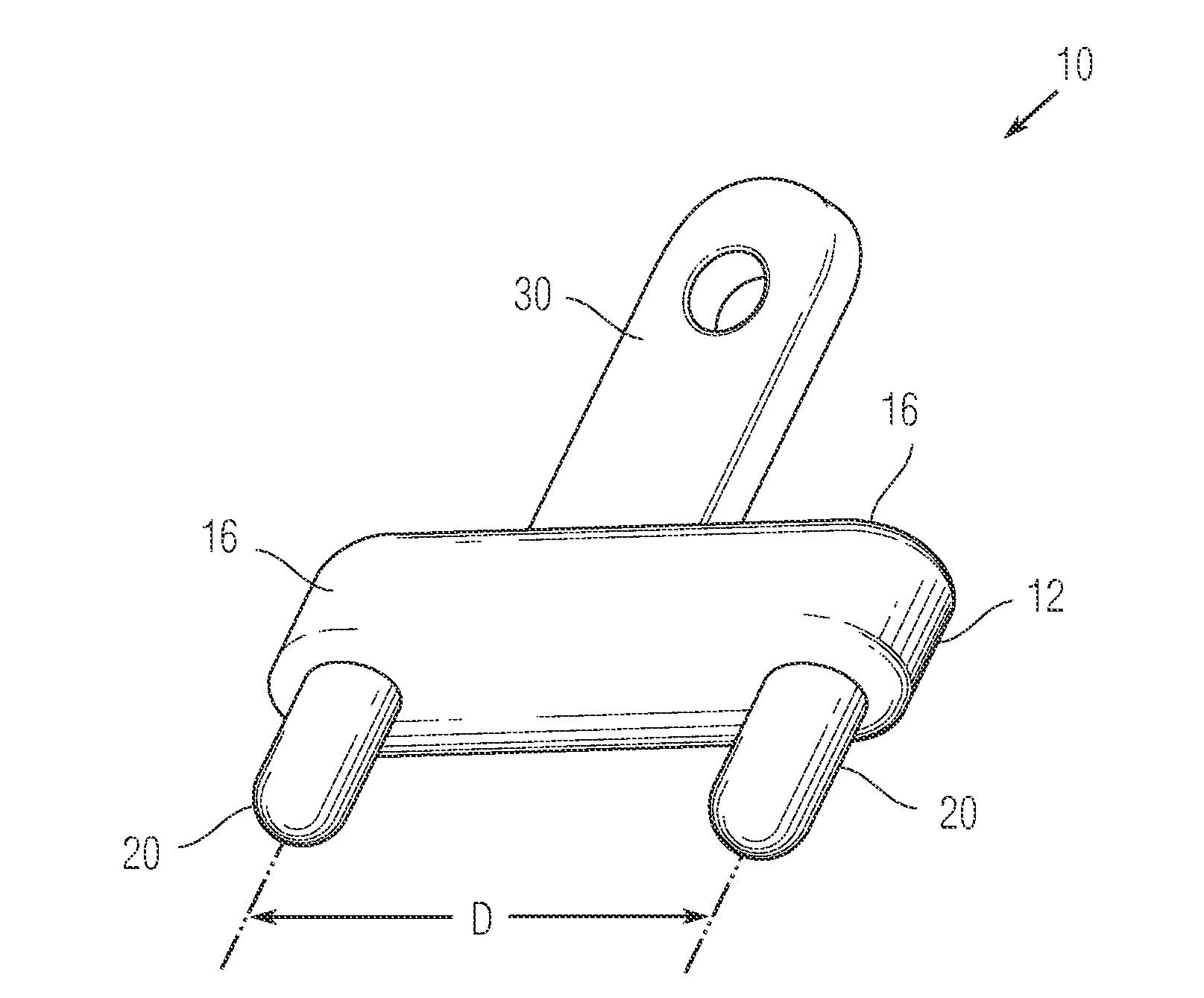
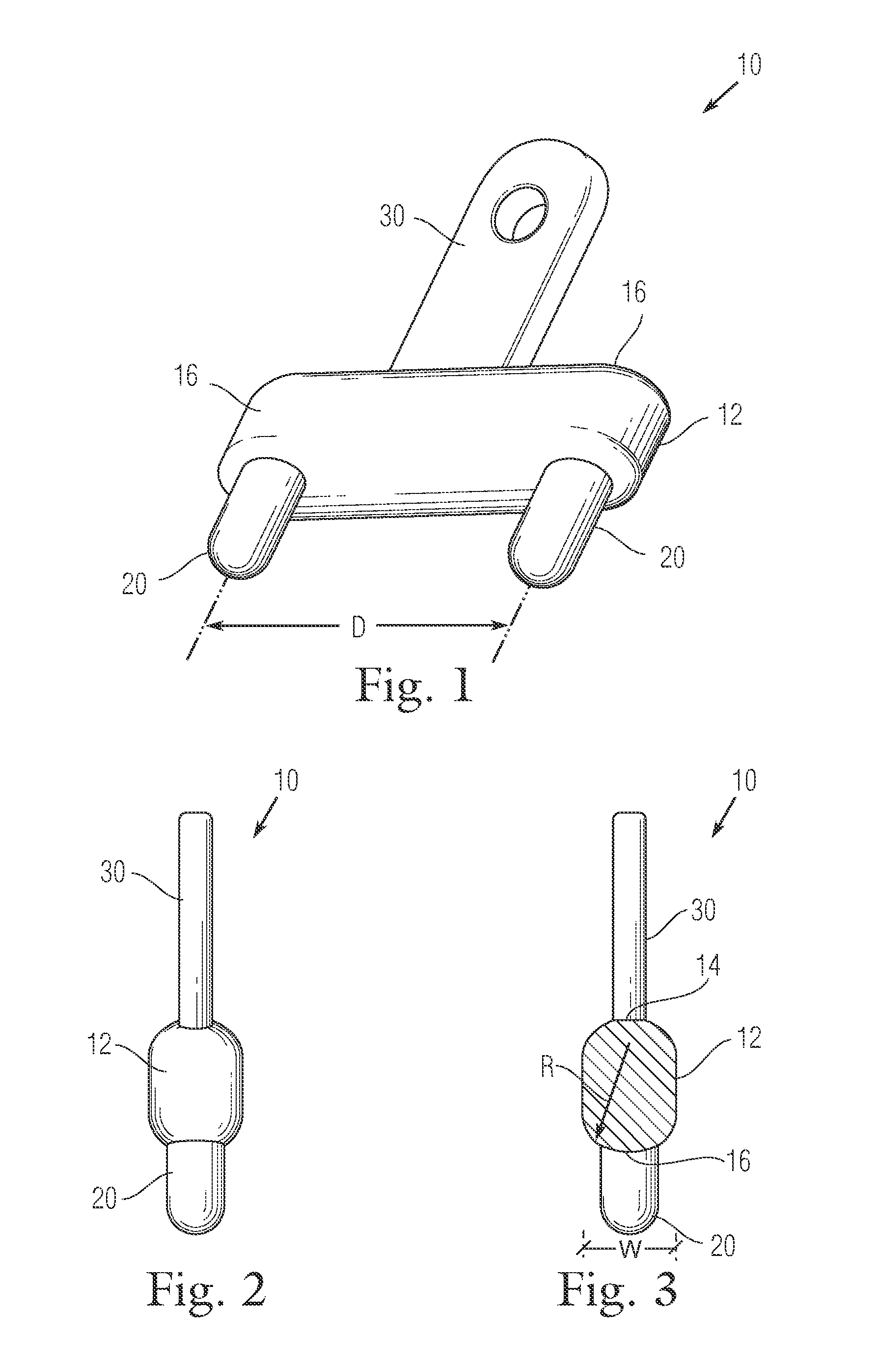
[0037]In its simplest and, perhaps, preferred form, the tool 10 of the present invention is made as a single unit formed of suitable material such as plastic (ABS, polystyrene, PVC, polycarbonate, polyurethane), wood or metal. Injection molded single part plastic construction may provide the most economical construction. However, unitary construction is limited in as much as the distance D and pin 20 diameter are fixed such that a given tool 10 is suitable for use with only a single sander platen dust extraction hole pattern. With reference to FIG. 7, an alternate embodiment of a tool 100 according to the present invention is depicted in which multiple pin configurations are possible. Tool 100 is provided with a longitudinal base member 112 substantially as described above with respect to base member 12 except that the base member 112 is selectively rotatable about its longitudinal axis X with respect to the handle 130. Additionally, two sets of pins 120 and 120′ are provided, one e...

embodiment 10

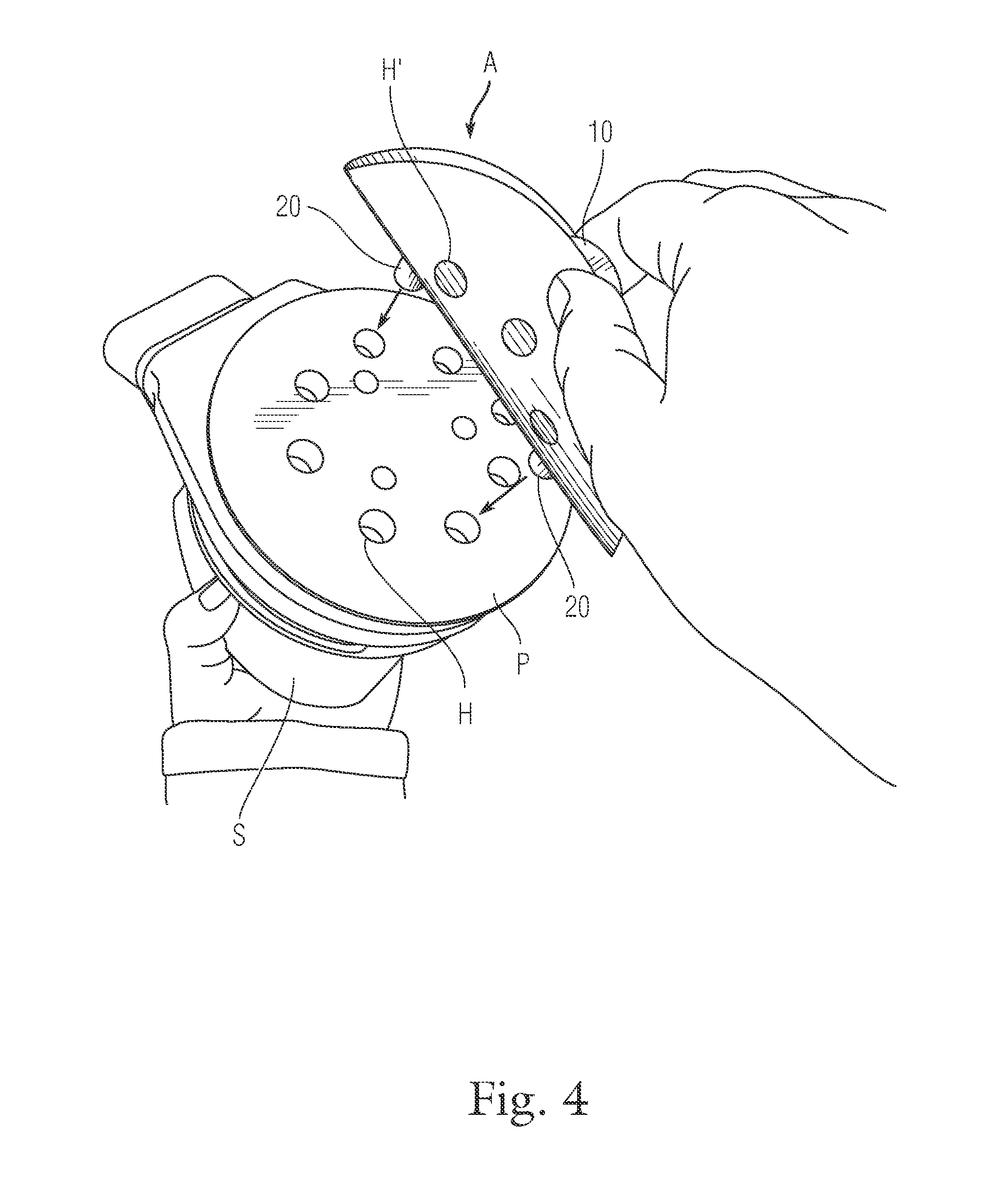
[0038]With reference to FIG. 8, another alternate embodiment of a tool 200 according to the present invention is depicted. Tool 200 is comprised of a planar base member 212, preferably circular in form and having a diameter substantially equal to that of the sanding disk with which it is intended to be used. Planar base member 212 is preferably constructed of a strong, lightweight polymer that is flexible in sheet form such as, for example, acrylic, polyethylene, polycarbonate, or polyurethane. Alternately, planar base member 212 the may be formed of a rigid sheet plastic bent or bowed and fixed into a curved shape that resembles a traditional hard taco shell. A pair of pins 220 substantially similar to pins 20 are provided extending from one side of the planar base member 212. Pins 220 are preferably situated symmetrically with respect to the center of the preferably circular planar member and are positioned and sized for cooperative insertion into the dust extraction holes H of a ...


PUM

PropertyMeasurementUnit
sizeaaaaaaaaaa
sizeaaaaaaaaaa
sizeaaaaaaaaaa

Abstract

A sanding disk alignment tool for aligning a sanding disk having a plurality of dust collection holes to a sander platen having a cooperative plurality of holes is disclosed with a method of use. The tool includes a base member having at least two pins sized and positioned for cooperative insertion into the pluralities of dust collection holes extending from a surface thereof. The method includes the steps of inserting the pins through two of the dust collection holes in the sanding disk from the abrasive side, bending the sanding disk around the tool, inserting the pins into through two of the plurality of dust collection holes in the sander platen and advancing the tool and disk to engage the platen. Once initially engaged to the platen, the bend in the disk is released and the sides of the disk are laid down onto the platen, after which the tool is removed.

Description

CROSS-REFERENCE TO RELATED APPLICATION(S)[0001]The present application derives priority from U.S. provisional application Ser. No. 61 / 641,100 filed May 1, 2012.BACKGROUND OF THE INVENTION[0002]1. Field of the Invention[0003]The present invention relates to the field of handheld power tools and, more specifically to a device for use in conjunction with a power sanding tool for proper alignment of the coated abrasive.[0004]2. Description of the Background[0005]Sanding, the process of smoothing and shaping a material surface by rubbing with an abrasive, has many applications in industrial production and finishing of materials such as wood, metal and fiberglass. Commonly done by hand with an abrasive coated paper or cloth (i.e., sandpaper), the process can be accelerated and the results improved with the use of handheld power tools that mount and move the sandpaper on the work surface. Power sanders are available in a wide variety of designs including palm sanders such as the random orb...

Claims


Application Information

Patent Timeline
Patent Type & Authority Applications(United States)
IPC IPC(8): B24B23/00
CPCB24B23/005B24D9/085
Inventor TURNER, CHRIS R.
Owner TURNER CHRIS R
Why Eureka
Eureka Blog
Learn More