Seat fitting for a motor vehicle seat

a technology for motor vehicles and seat fittings, which is applied in the direction of vehicle components, vehicle arrangement, gearing, etc., can solve the problems of swiveling of the top part of the seat fitting, and achieve the effects of low cost, easy production and cost saving

Active Publication Date: 2014-06-12
ADIENT US LLC
View PDF8 Cites 6 Cited by
  • Summary
  • Abstract
  • Description
  • Claims
  • Application Information

AI Technical Summary

Benefits of technology

[0026]According to a particularly advantageous design of the invention, it is provided that the stop cam and the cam receptacle are formed such that during an adjustment, the stop cam moved on a cycloid-shaped path relative to the cam receptacle, comes into contact with the side surface of the cam receptacle in the zone of the movement path, in which the portion of the movement of the path oriented in the peripheral direction is greater than the portion of the movement path oriented in the radial direction. According to this design of the invention, the cam receptacle and the stop cam are matched to each other such that these come in contact against each other when the portion of the movement pointing in the peripheral direction is greater than the portion of the movement oriented in the radial direction. As a result, a seizing of the stop cam and cam receptacle can be prevented in a particularly reliable manner. When the stop cam and cam receptacle come into contact with each other, the danger of seizing can exist if the portion of the movement of the stop cam in the radial direction is significantly greater than the portion of the movement in the peripheral direction.
[0027]Basically, the advantages attained by using the invention are already attained due to the design of the seat fitting having a cam receptacle and a stop cam. Beyond that, there are numerous further designs, wherein for example two or more cam receptacles of the same length can be provided with associated stop cams. According to a particularly advantageous design of the invention, however, several cam receptacles, preferably two cam receptacles, in particular, preferably three cam receptacles having different lengths are arranged in the peripheral direction on the ring gear or gear wheel. This design of the invention allows seat fittings with different adjustment zones to be defined with identical components, in particular with the provision of only one stop cam, depending on the installation position of the gear wheel relative to the ring gear, namely with the selection of the cam receptacle in which the preferably one cam is arranged. Thus, this design of the invention allows a cost-effective production of a seat fitting, which with identical components can be adapted to different manufacturer specifications.
[0028]The design of the fitting top part, or respectively fitting bottom part, to be connected to the seating part and the backrest, is in principle freely selectable. According to a particularly advantageous design of the invention, the fitting top part however, is formed integrally with the ring gear and / or the fitting bottom part is formed integrally with the gear wheel. Using this design of the invention, an additional assembly of the ring gear and / or the gear wheel to the fitting top part and / or fitting bottom part can be omitted. The thusly further developed seat fitting can be produced particularly easily and cost-effectively, because in particular, additional assembly steps can be omitted.
[0029]The design of the eccentric for the drive of the gear wheel relative to the ring gear can be basically formed in any manner. According to a particularly advantageous design of the invention, however, the eccentric has a catch and two wedge segments. Depending on the design of the catch and the orientation thereof relative to the wedge segments, which causes an eccentric arrangement of the gear wheel relative to the longitudinal axis of the ring gear, an adjustment zone of the drive shaft can be defined in the range of which an adjustment does not result in a direct displacement of the fitting top part relative to the fitting bottom part. The use of a catch in conjunction with two wedge segments is distinguished by the simple construction and reliable function.
[0030]In order to guarantee a reliable abutment of the wedge segments in the slide ring arranged in the bore of the gear wheel, according to a particularly advantageous design of the invention it is provided that these are pushed apart in the peripheral direction using a spring element, in particular an omega spring. The use of an omega spring can be implemented in a particularly simple and cost-effective manner, wherein due to the design thereof, this can be arranged in the seat fitting in a particularly space-saving manner.

Problems solved by technology

This results in a drive of the eccentric, which causes a rolling adjustment of the gear wheel relative to the ring gear, which results in the fitting top part being swivelled relative to the fitting bottom part.

Method used


Image

  • Seat fitting for a motor vehicle seat
  • Seat fitting for a motor vehicle seat
  • Seat fitting for a motor vehicle seat

Examples


first embodiment

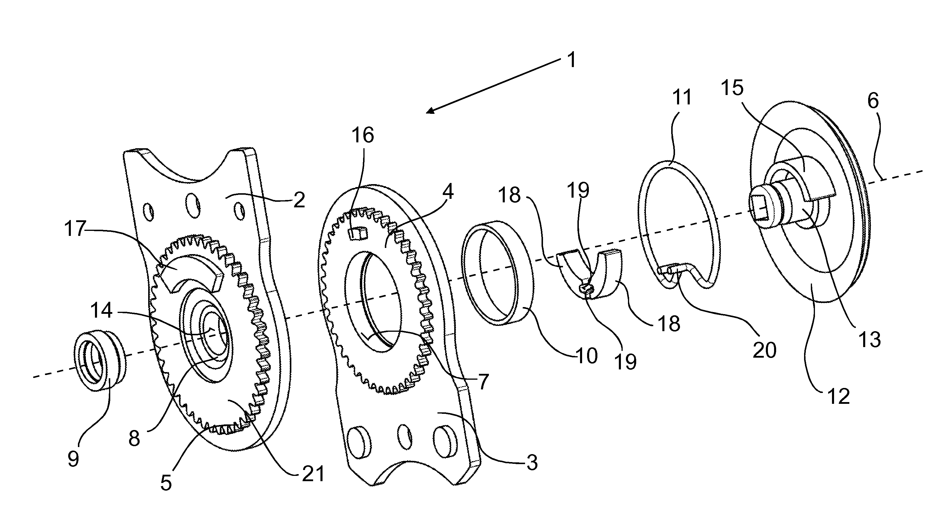
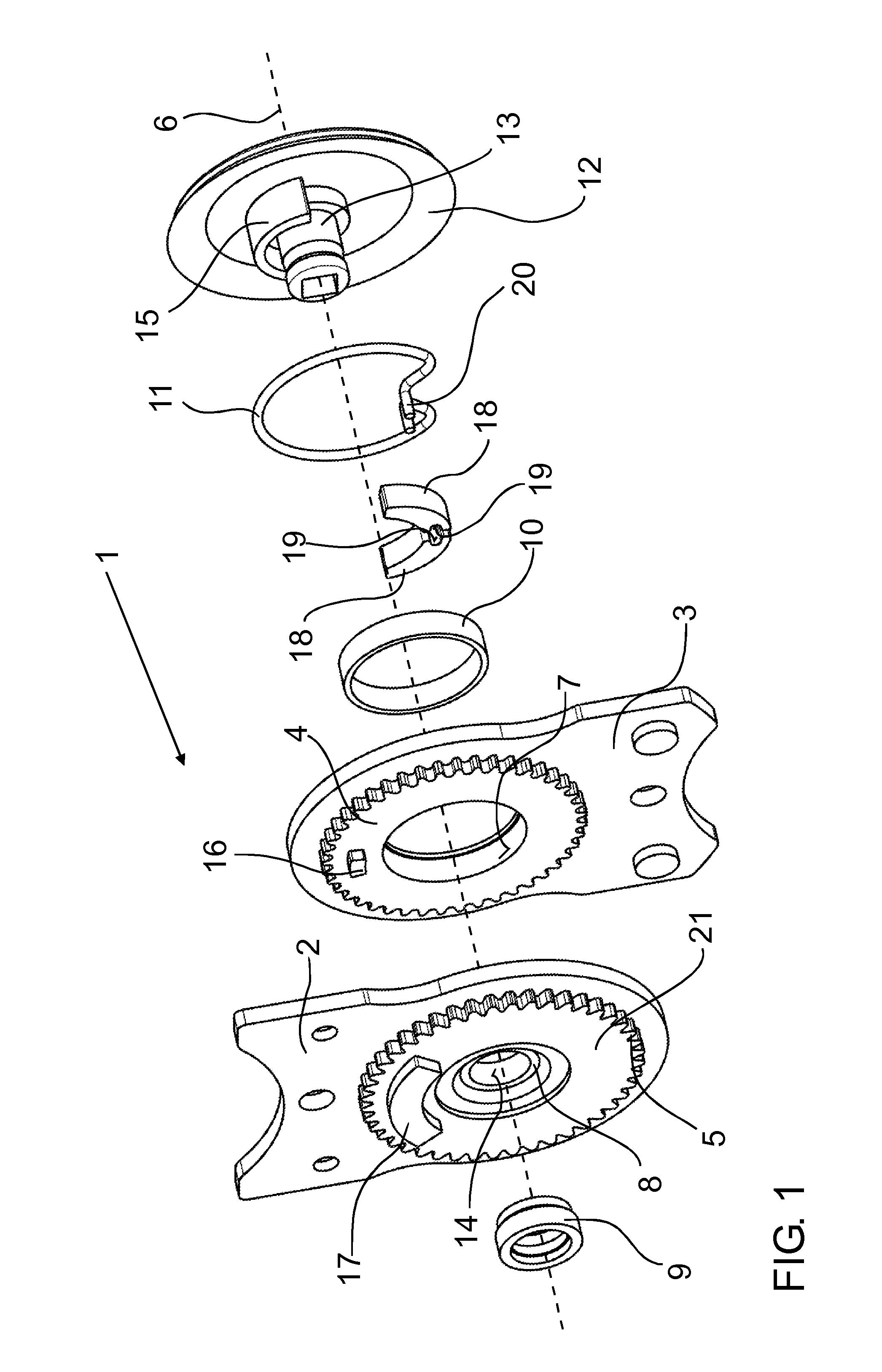
[0044]Referring to the drawings in particular, FIG. 1 shows a vehicle seat fitting 1 in an exploded representation. The vehicle seat fitting 1 has a fitting top part 2 and a fitting bottom part 3, which can be connected to a seating part, not shown here, and a backrest of a motor vehicle seat, also not shown.

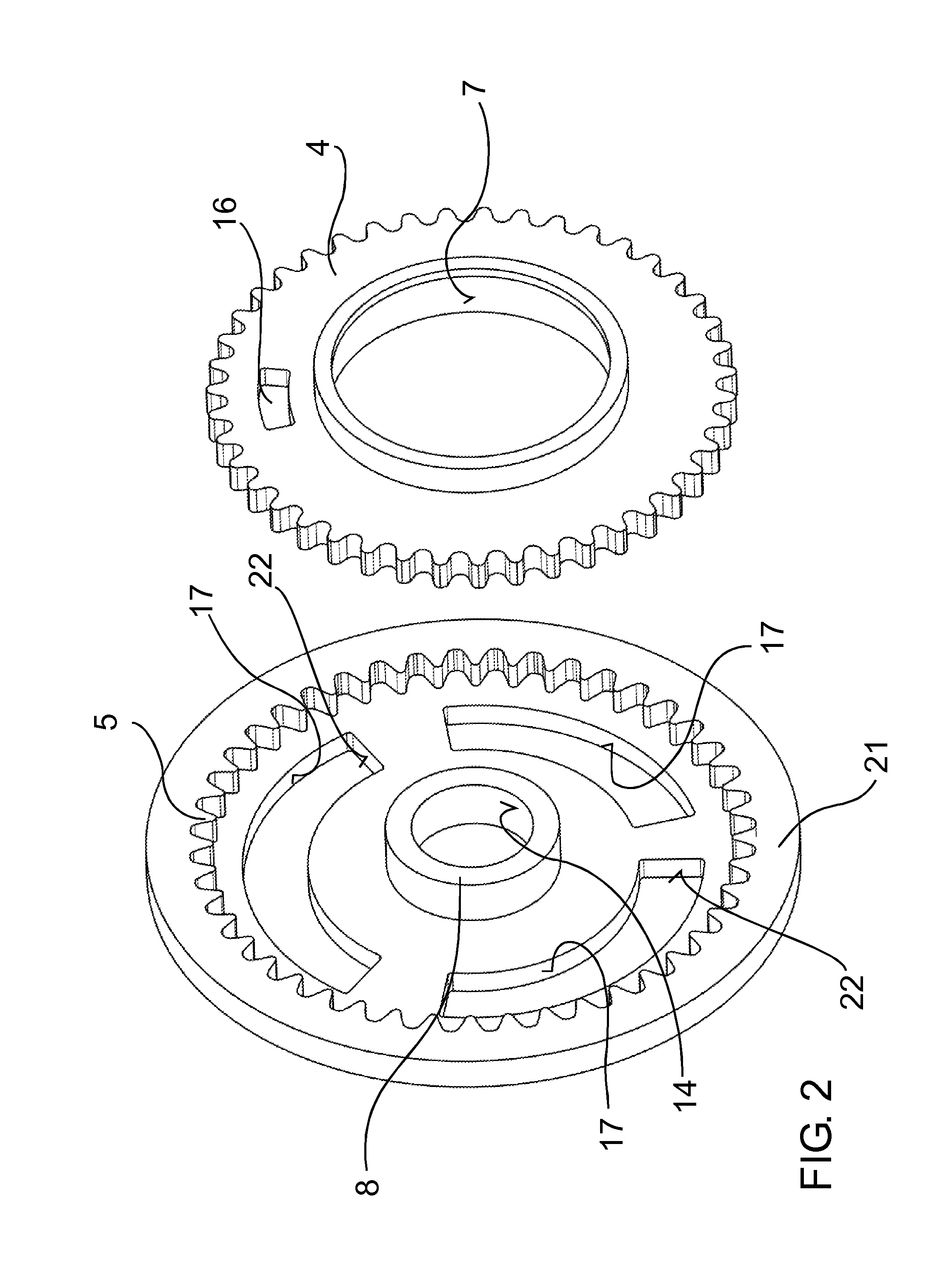
[0045]The fitting top part 2 has a ring gear 21 having an internal toothing 5. The ring gear 21 has a cam receptacle 17 in the zone between the internal toothing 5 and a bore 14 running axially to the ring gear 21. This receptacle extends coaxially to the bore 14.

[0046]The fitting bottom part 3 has a gear wheel 4 that on the side thereof facing toward the fitting top part 2, is provided with a stop cam 16, which in the assembled state of the vehicle seat fitting 1, in which the gear wheel 4 is arranged within the ring gear 21, runs within the cam receptacle 17. Here, the gear wheel 4 has a smaller number of teeth than the ring gear 21 such that with an eccentric arrangement of t...

second embodiment

[0053]FIG. 9 shows a vehicle seat fitting la in an exploded representation. In contrast to the seat fitting 1 shown in the FIGS. 1 to 8, the seat fitting 1a—which otherwise largely corresponds to the seat fitting 1—has a separate stop cam carrier formed as a stop ring 25, that is provided with a stop cam 16a.

[0054]In the assembled state of the seat fitting 1a, the stop ring 25 is connected, secured against rotation, to the gear wheel 4a such that the stop cam 16a is also fixed relative to the gear wheel 4a. For this purpose, a gear wheel 4a has a deepening 27 having a “flower-like” contouring 26, and the stop ring 25 has a correspondingly formed shape, whereby a form locking arises in the peripheral direction.

[0055]The stop cam 16a projects from the stop ring 25 in the axial direction towards the ring gear 21a, wherein the stop cam 16a in the assembled state is arranged rotatably within the cam receptacle 17a of the ring gear 21a. The cam receptacle 17a formed circumferentially on ...


PUM


Abstract

A motor vehicle seat fitting includes a fitting top part with a ring gear (21) having internal toothing, a fitting bottom part with a gear wheel (4), having external toothing and which is in engagement with the ring gear, an eccentric arranged rotatably in a bore (7) of the bottom part running axially to the gear wheel, for rolling adjustment of the gear wheel relative to the hollow gear, and a drive shaft, which drives the eccentric and extends axially to the ring gear. A cam receptacle (17) is arranged on one of the gear wheel or the ring gear (21) and a stop cam (16), that engages in the cam receptacle, is arranged on the other of the gear wheel or ring gear, in a ring portion between the external toothing and the bore and on the ring gear in a zone which may overlap the ring portion.

Description

CROSS REFERENCE TO RELATED APPLICATIONS[0001]This application is a United States National Phase Application of International Application PCT / EP2012 / 063716 filed Jul. 12, 2012 and claims the benefit of priority under 35 U.S.C. §119 of German Patent Application DE 10 2011 051 990.4 filed Jul. 20, 2011, the entire contents of which are incorporated herein by reference.FIELD OF THE INVENTION[0002]The invention relates to a seat fitting for a motor vehicle seat, with[0003]a fitting top part with a ring gear that has internal toothing,[0004]a fitting bottom part with a gear wheel, which has external toothing and which is in engagement with the ring gear,[0005]an eccentric arranged rotatably in a bore of the fitting bottom part running axially to the gear wheel for rolling adjustment of the gear wheel relative to the ring gear, and[0006]a drive shaft, which drives the eccentric and extends axially to the ring gear.BACKGROUND OF THE INVENTION[0007]Seat fittings of the initially named type, ...

Claims


Application Information

Patent Timeline
Patent Type & Authority Applications(United States)
IPC IPC(8): B60N2/225
CPCB60N2/2252B60N2/2254
Inventor WINGENSIEFEN, WILHELM
Owner ADIENT US LLC
Why Eureka
Try Eureka