Clear ice maker

a clear, ice maker technology, applied in the field of ice makers, can solve the problems of high cost, unsatisfactory taste and appearance, and cloudy appearance of ice cubes, and achieve the effect of high-efficiency system

a clear, ice maker technology, applied in the field of ice makers, can solve the problems of high cost, unsatisfactory taste and appearance, and cloudy appearance of ice cubes, and achieve the effect of high-efficiency system

US20140165601A1Active Publication Date: 2014-06-19WHIRLPOOL CORP

Image

  • Clear ice maker
  • Clear ice maker
  • Clear ice maker

Examples


Embodiment Construction

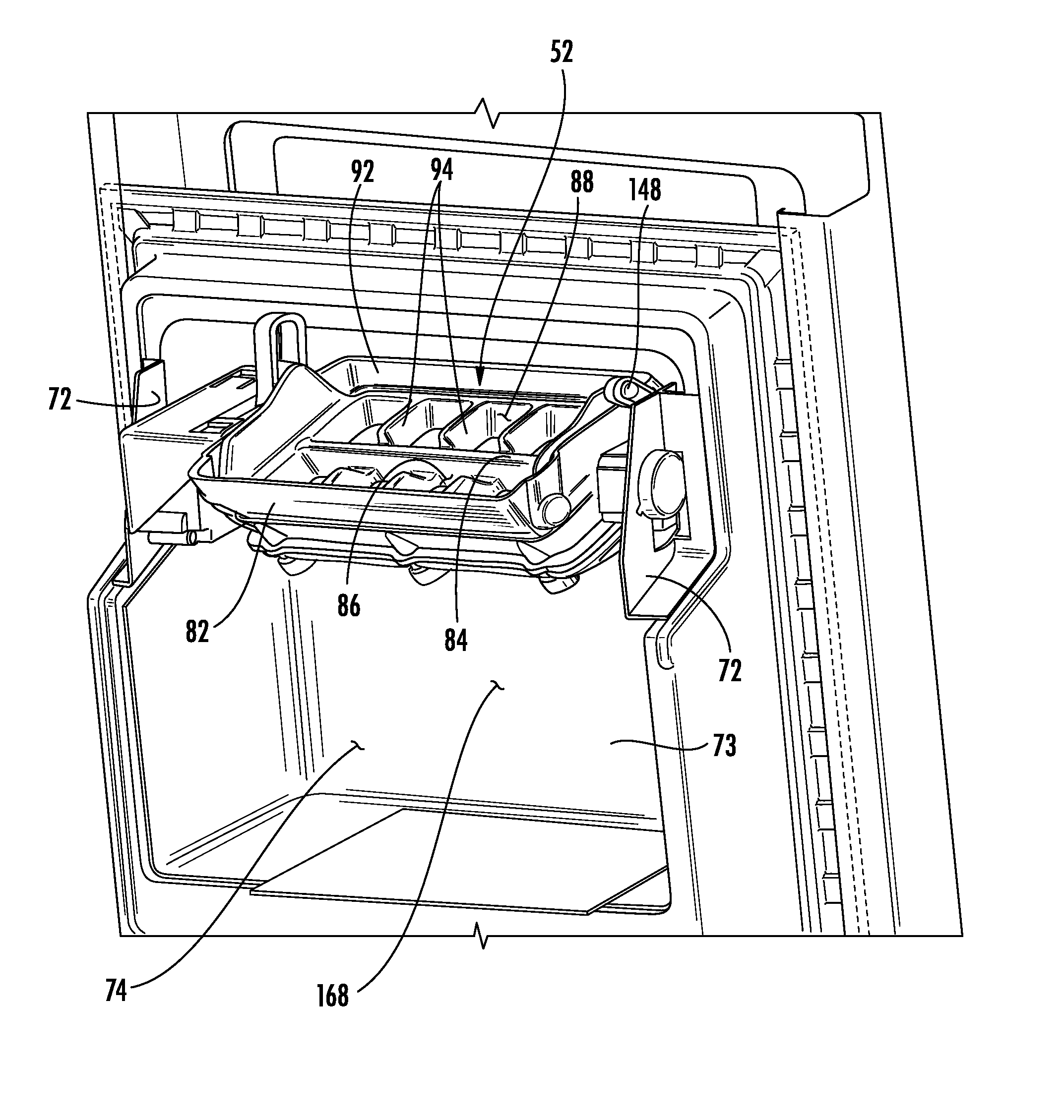
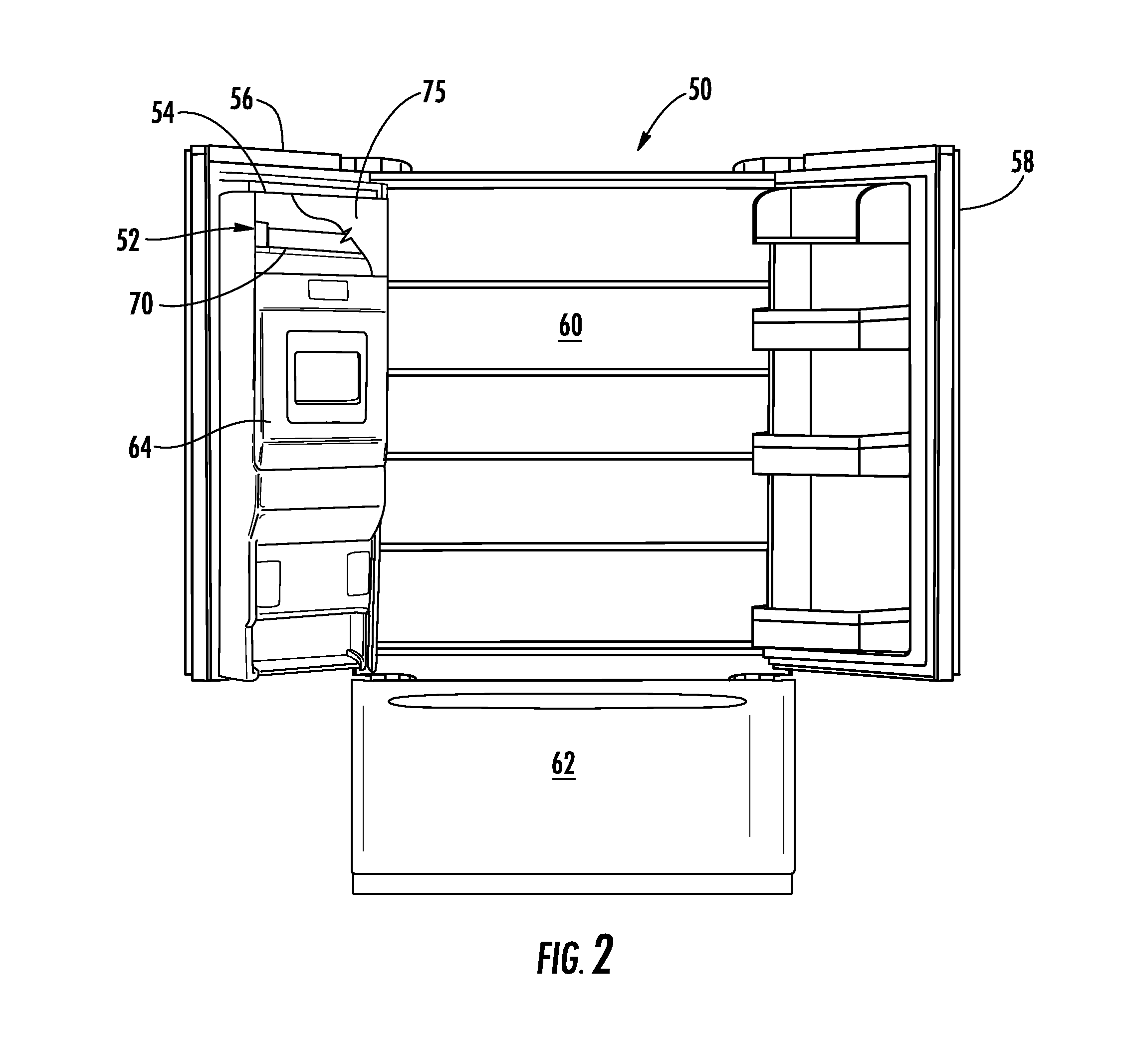
[0052]For purposes of description herein, the terms “upper,”“lower,”“right,”“left,”“rear,”“front,”“vertical,”“horizontal,” and derivates thereof shall relate to the ice maker assembly 52, 210 as oriented in FIG. 2 unless stated otherwise. However, it is to be understood that the ice maker assembly may assume various alternative orientations, except where expressly specified to the contrary. It is also to be understood that the specific devices and processes illustrated in the attached drawings, and described in the following specification are simply exemplary embodiments of the inventive concepts defined in the appended claims. Hence, specific dimensions and other physical characteristics relating to the embodiments disclosed herein are not to be considered as limiting, unless the claims expressly state otherwise.

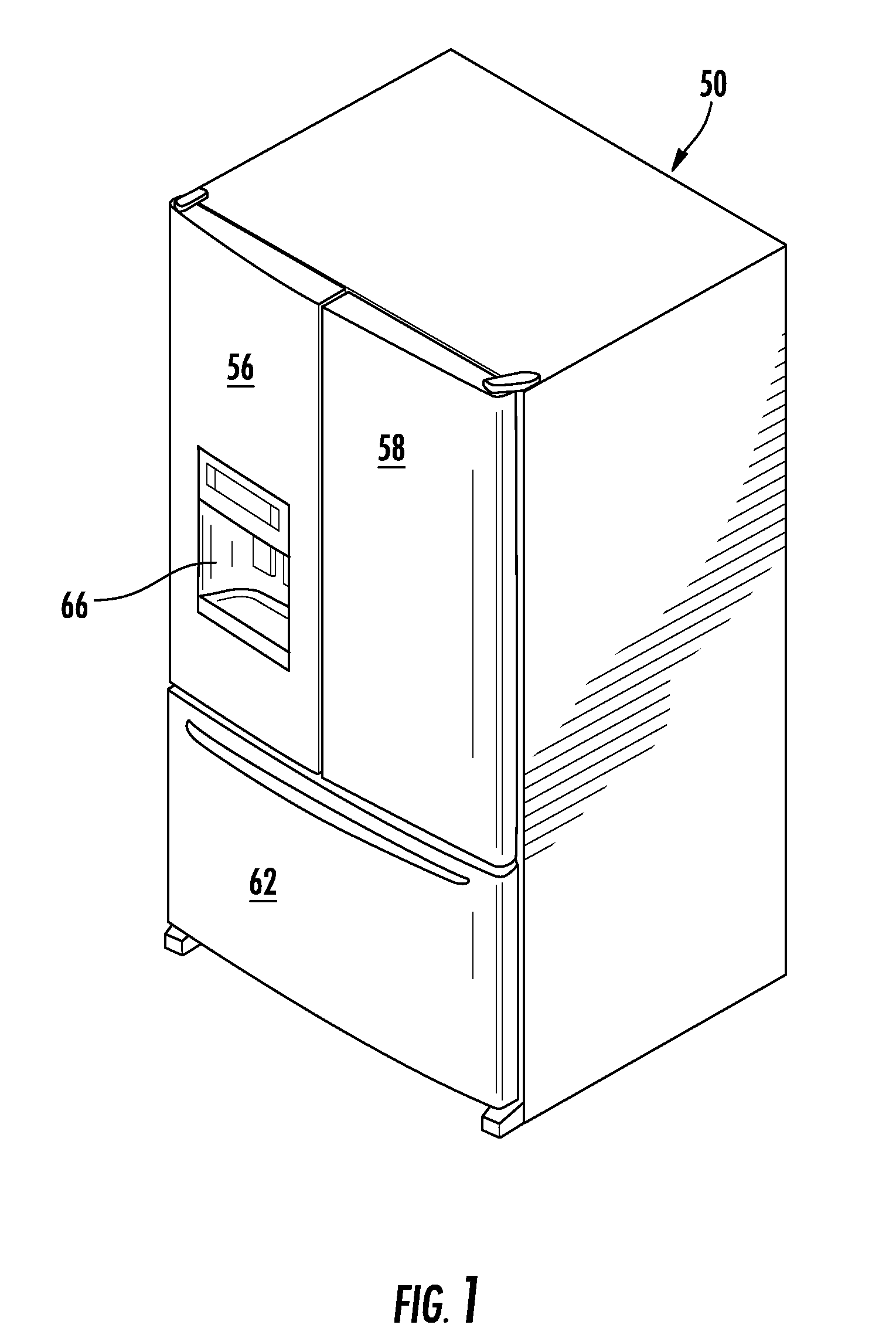
[0053]Referring initially to FIGS. 1-2, there is generally shown a refrigerator 50, which includes an ice maker 52 contained within an ice maker housing 54 inside the refri...


PUM


Abstract

An ice making tray has an array of individual ice cube compartments. A mechanical oscillating mechanism is coupled to the tray and rotates the tray from a horizontal plane in opposite directions along an axis through an angle φ of about 20° to 40°, such that water in the tray moves between ice cube compartments. The frequency of oscillation (ω) is harmonically related to the frequency of movement of water in the tray and is about equal to or about twice the frequency of movement of water in the tray. In a preferred embodiment, the floor of the tray is a thermally conductive material in contact with a thermoelectric plate used to freeze the water as well as being subsequently heated to release the formed ice cubes.

Description

RELATED APPLICATIONS[0001]The present application is related to, and hereby incorporates by reference the entire disclosures of, the following applications for United States Patents: U.S. patent application Ser. No. ______, entitled “Ice Maker with Rocking Cold Plate,” filed on even date herewith (attorney docket no. SUB-01625-US-NP); U.S. patent application Ser. No. ______, entitled “Clear Ice Maker with Warm Air Flow,” filed on even date herewith (attorney docket no. SUB-01518-US-NP); U.S. patent application Ser. No. ______, entitled “Clear Ice Maker with Varied Thermal Conductivity,” filed on even date herewith (attorney docket no. PAT-00123-US-NP); U.S. patent application Ser. No. ______, entitled “Clear Ice Maker,” filed on even date herewith (attorney docket no. SUB-02962-US-NP); U.S. patent application Ser. No. ______, entitled “Layering of Low Thermal Conductive Material on Metal Tray,” filed on even date herewith (attorney docket no. SUB-02939-US-NP); U.S. patent applicatio...

Claims


Application Information

Patent Timeline
19 Jun 2014
Publication
US20140165601A1
IPC
F25C1/20; F25B21/04; F25C1/10
CPC
F25C1/20; F25C1/10; F25B21/04; F25B21/02; F25C5/06; F25C5/22; F25C2305/0221; F25C5/08
Inventors
BOARMAN, PATRICK J.; THOMAS, MARK E.