Edge band cutting device

a cutting device and edge band technology, applied in the field of cutting devices, can solve the problems of achieve the effects of reducing manufacturing and assembly difficulties, reducing manufacturing costs, and improving supportability

Inactive Publication Date: 2014-06-19
LIN CHIN CHI
View PDF0 Cites 7 Cited by
  • Summary
  • Abstract
  • Description
  • Claims
  • Application Information

AI Technical Summary

Benefits of technology

[0007]The object of this invention is to provide an edge band cutting device that can adjust the cut length of an edge band, that can improve the supportability, and that has a simple structure.
[0009]By moving the adjustable positioning member to align with the start end of the edge band, the cut length of the edge band can be adjusted to eliminate further operation performed on the cut end of the edge band. By adjusting the adjustable supporting member, the cut length of the edge band also can be adjusted, and the supportability is improved.

Problems solved by technology

The positioning unit has numerous components, and is troublesome to manufacture and assemble.

Method used


Image

  • Edge band cutting device
  • Edge band cutting device
  • Edge band cutting device

Examples


Embodiment Construction

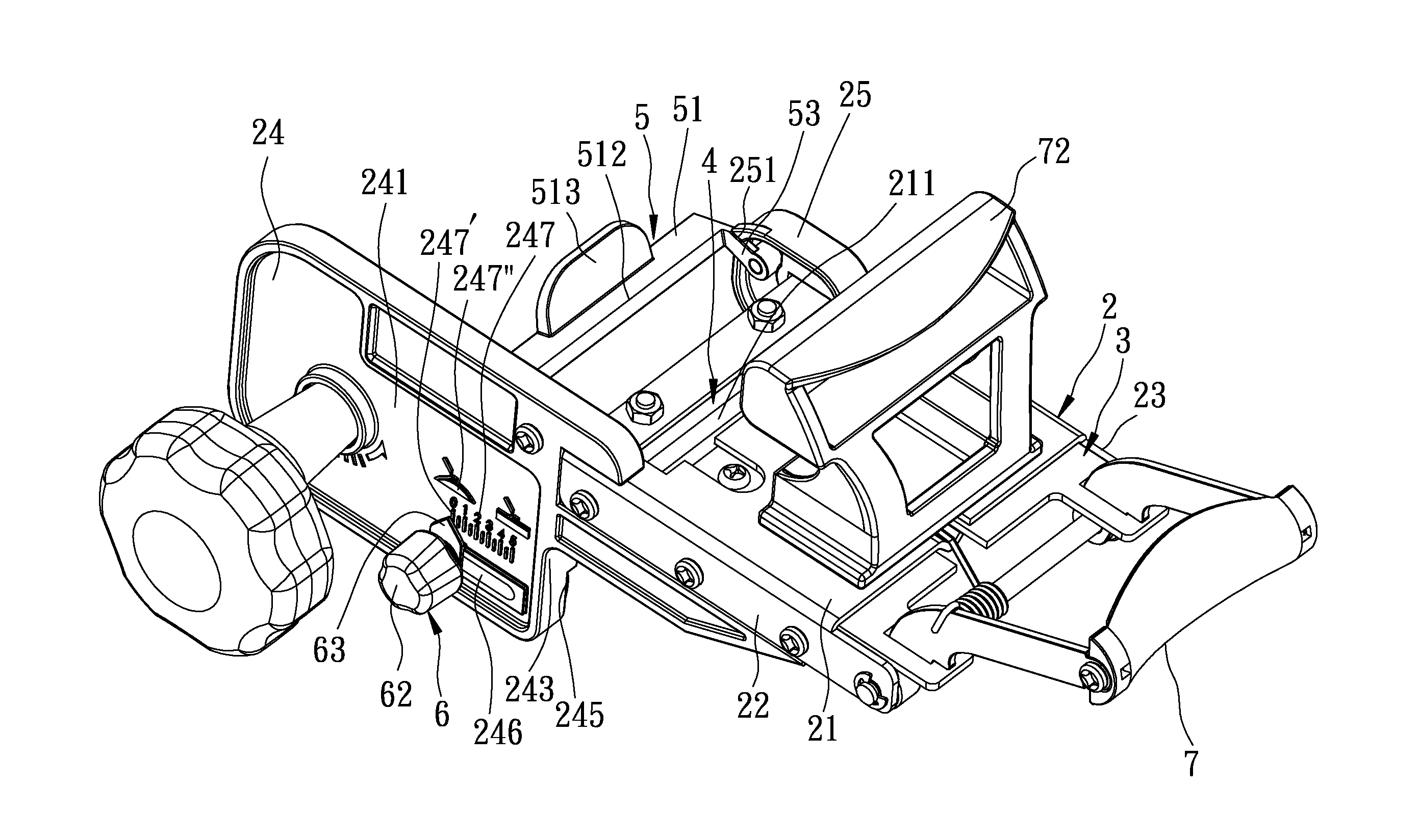
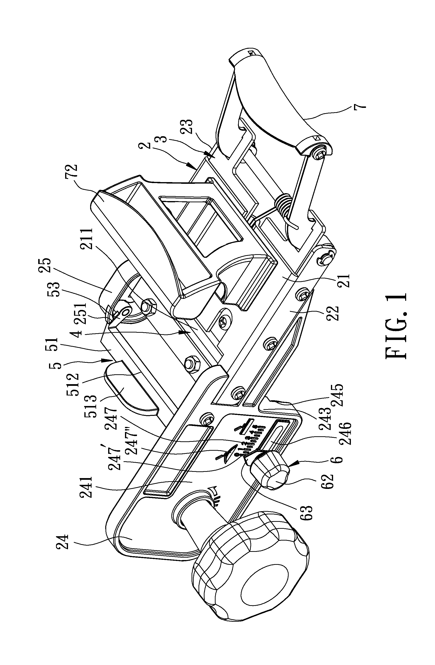
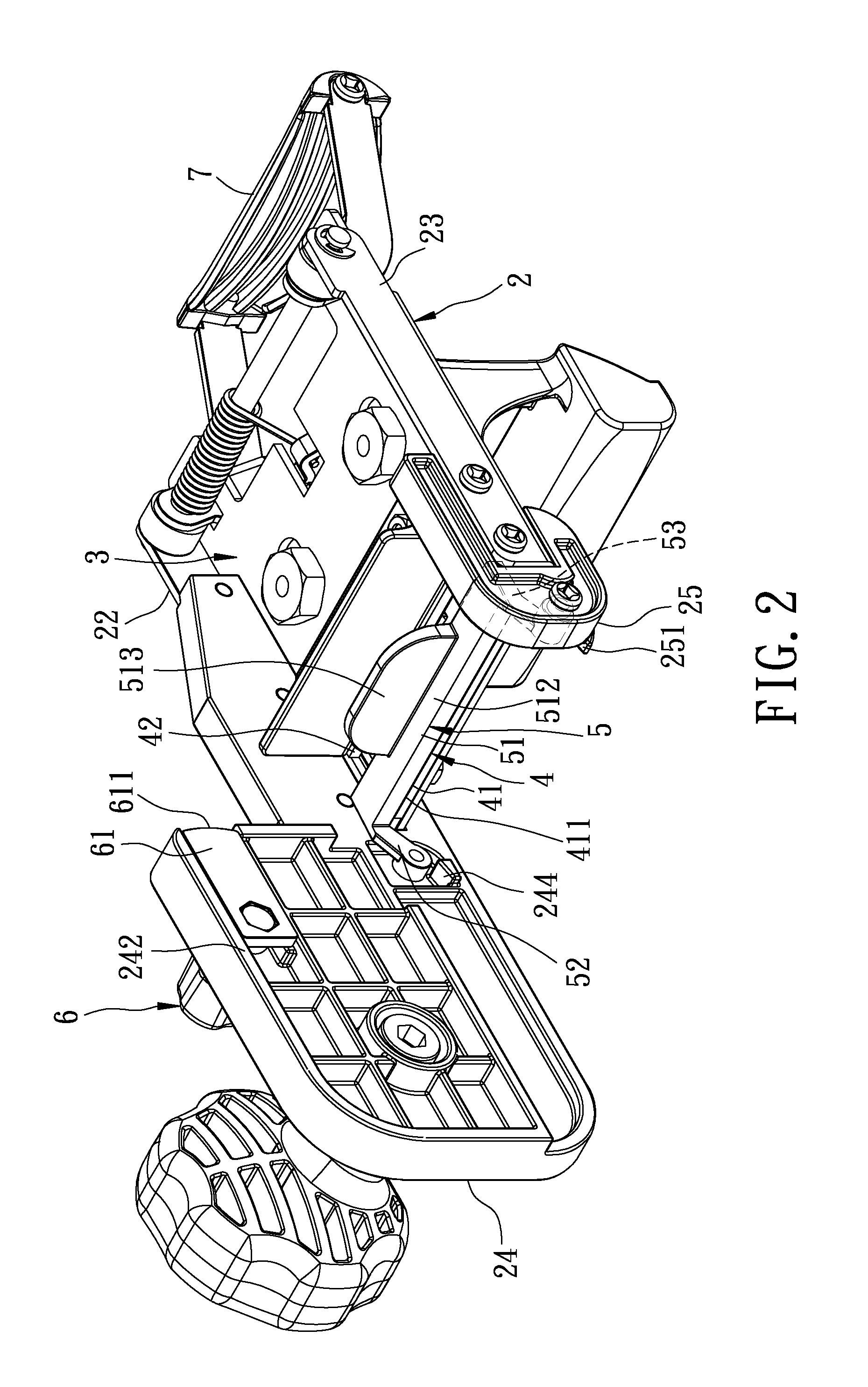
[0021]Referring to FIGS. 1, 2, 3, and 4, the preferred embodiment of an edge band cutting device according to this invention includes a fixed unit 2, a movable plate 3, a cutter unit 4, an adjustable positioning unit 5, an adjustable supporting unit 6, and a handle unit 7. In FIG. 1, the adjustable positioning unit 5 is removed from the cutter unit 4. In FIGS. 2, 3, and 4, the adjustable positioning unit 5 abuts against the cutter unit 4.

[0022]The fixed unit 2 includes a base plate 21 having an opening 211, a top plate 22 connected to the base plate 21, a main bottom plate 23 connected to the base plate 21 and disposed under the top plate 22, a pressing plate 24 connected to the top plate 22 and perpendicular to the base plate 21, and an auxiliary bottom plate 25 connected to the main bottom plate 23. The pressing plate 24 and the auxiliary bottom plate 25 have aligned limiting portions 244, 251, respectively.

[0023]With further reference to FIG. 5, the pressing plate 24 further incl...


PUM

PropertyMeasurementUnit
lengthaaaaaaaaaa
cut lengthaaaaaaaaaa
timeaaaaaaaaaa

Abstract

An edge band cutting device includes a fixed unit, a movable plate movable on a base plate of the fixed unit, a cutter unit including a main cutter and an auxiliary cutter, an adjustable positioning unit abutting removably against the main cutter, and an adjustable supporting unit disposed on the fixed unit. The base plate has an opening. A space between the main cutter and the auxiliary cutter is aligned with the opening. The adjustable supporting unit includes an adjustable supporting member disposed movably on a pressing plate of the fixed unit, and a locking member for locking the adjustable supporting member on the pressing plate to allow the adjustable supporting member to be retracted into or extended from the pressing plate.

Description

BACKGROUND OF THE INVENTION[0001]1. Field of the Invention[0002]This invention relates to a cutting device, and more particularly to an edge band cutting device.[0003]2. Description of the Related Art[0004]DE202011108007.6 discloses an edge band cutting device, which includes a fixed unit, a moving unit, a cutter unit, and an adjusting unit, and which, through operation of an adjusting member, the length of a segment of the edge band between a cut end and an adhered terminal end can be controlled to be equal to the distance between the start end and the adhered terminal end so that, when the segment is adhered to the plank, the cut end can be brought into intimate contact with the start end without further cutting operation performed on the segment, thereby reducing the machining costs.[0005]The supportability of the edge band cutting device needs to be improved, and a more convenient adjustment is required.[0006]Furthermore, the aforesaid edge band cutting device further includes a...

Claims


Application Information

Patent Timeline
Patent Type & Authority Applications(United States)
IPC IPC(8): B26D7/26
CPCB26D1/065B26D5/10B26D7/2628B26D7/27B26D2001/0066B27D5/003Y10T83/849Y10T83/9488
Inventor LIN, CHIN-CHI
Owner LIN CHIN CHI
Why Eureka
Try Eureka