
Fuel system for an excavator

a fuel system and excavating technology, applied in the direction of liquid fuel feeders, machines/engines, combustion air/fuel air treatment, etc., can solve the problems of inability to operate equipment, degrade the start-up performance of the engine, and indicate the error signal on the instrument board of the operator cab

Active Publication Date: 2014-06-19
VOLVO CONSTR EQUIP
View PDF4 Cites 2 Cited by
  • Summary
  • Abstract
  • Description
  • Claims
  • Application Information

AI Technical Summary

Benefits of technology

The patent describes a system that improves engine performance by using remaining fuel after engine start-up. This system eliminates the need for a hand pump to start the engine, reducing the risk of damage to parts and ensuring reliability. The system also prevents internal leakage of oil and damage to the engine caused by excessive manipulation of the hand pump. Overall, this system improves engine performance and reliability.

Problems solved by technology

In addition, in the case where the fuel is not remained in the engine, the start-up performance of the engine is degraded, so that an error signal is indicated on an instrument board of an operator cab or the operation of the equipment becomes impossible.
For this reason, since an operator is required to manually manipulate a hand pump (referring to a prime pump operated manually) for start-up to supply fuel to the engine, and manipulate the hand pump, whenever necessary, he or she suffers from a great inconvenience.
In addition, since a pressure is significantly increased due to the excessive manipulation of the hand pump and the hand pump is used as occasion demands, internal leakage of fuel and damage of the hand pump may be caused.
Besides, there may occur a problem in that the check valve installed between the fuel tank and the hand pump is damaged.

Method used


Image

  • Fuel system for an excavator
  • Fuel system for an excavator

Examples


Embodiment Construction

Technical Problems

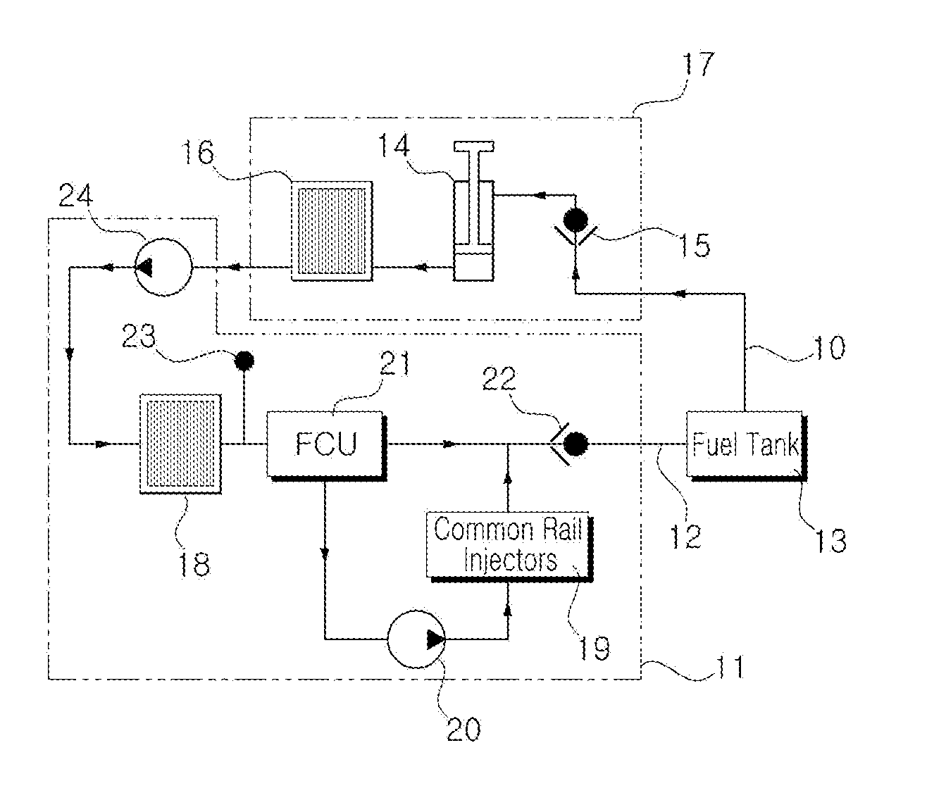
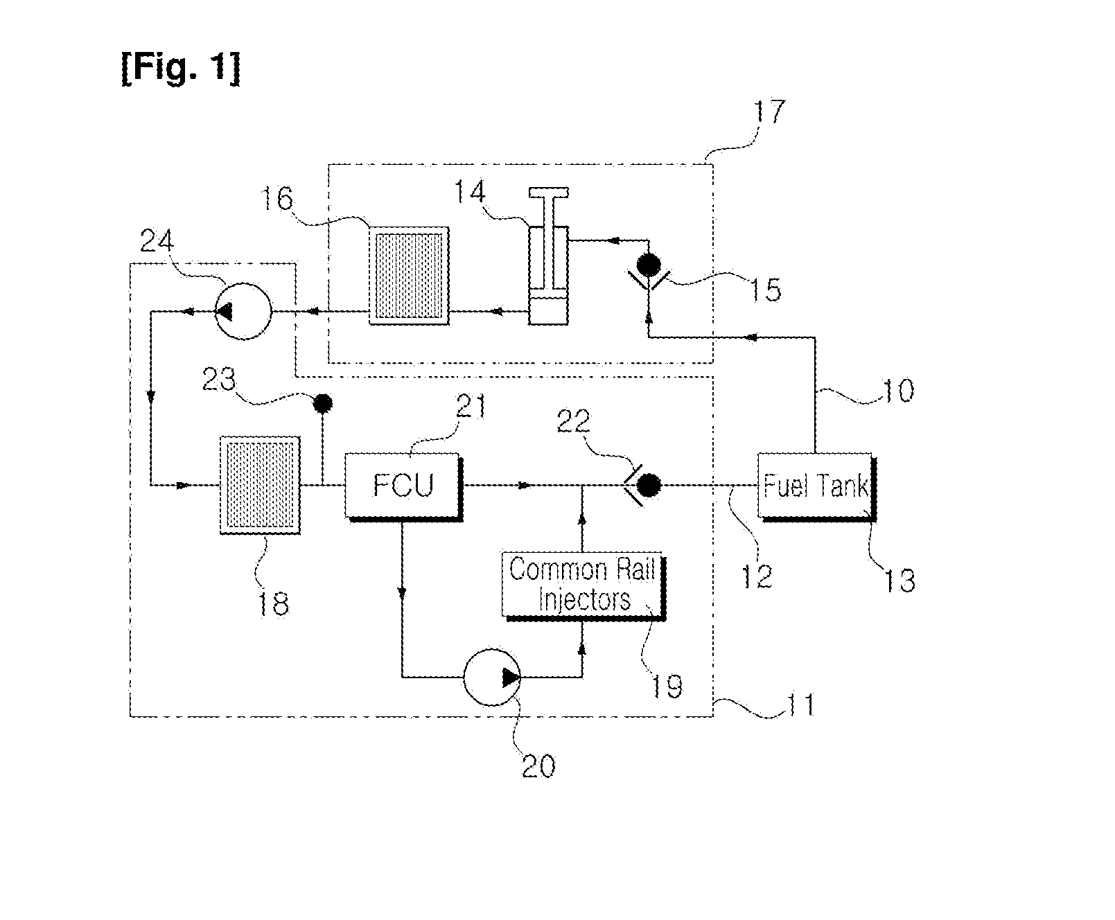
[0006]Accordingly, the present invention has been made to solve the aforementioned problem occurring in the prior art, and it is an object of the present invention to provide a fuel system for an excavator in which in the case where the equipment is not operated by the start-off of the engine, the remaining fuel that is remained after being used on the engine remains on the common rail injector side without being returned to the fuel tank so that the start-up performance of the engine can be improved.

[0007]Another object of the present invention is to provide a fuel system for an excavator in which the manipulation of the hand pump is not required to start up the engine, thereby improving convenience, and internal leakage of oil and damage of parts such as the hand pump, the check valve, and the like due to a rise of pressure according to an excessive manipulation of the hand pump can be prevented.

Technical Solution

[0008]To accomplish the above object, in accordanc...


PUM


Abstract

A fuel system is disclosed which is adapted to improve engine ignition properties by ensuring that, when the engine ignition is turned off, residual fuel left over in the engine area after use is not returned to the fuel tank but instead remains in a common rail injector area. The fuel system for an excavator according to the present invention comprises: a fuel tank having a fuel supply line for discharging fuel and a return line for returning residual fuel after combustion in the engine area; a water-fraction separator which is provided downstream of the fuel tank, removes the water fraction contained in the fuel that is sucked in, and consists of a hand pump that is linked to the fuel supply line and of a first filter that is linked to the hand pump and filters out extraneous material in the fuel; an injection pump which is provided downstream of the water-fraction separator and which provides an injector with a high pressure supply of the fuel, from which the extraneous material has been filtered out on passing through the first filter and a second filter linked thereto, such that said fuel is sprayed into an engine combustion chamber; a fuel control unit which is respectively linked to the second filter and the injection pump and controls the injection pump so as to control the volume of fuel supplied to the injector; and a check valve which is provided in the return line and ensures that, when the equipment is made to stop working because the engine ignition is turned off, residual fuel left over in the engine area after use is not returned to the fuel tank along the return line but instead remains in the injector area.

Description

FIELD OF THE INVENTION[0001]The present invention relates to a fuel system for an excavator. More particularly, the present invention relates to a fuel system for an excavator, in which in the case where the equipment is suspended in operation so as to be left to stand idle by the start off of an engine, the remaining fuel remained after being combusted on the engine stays on a common rail injector side of the engine without being returned to a fuel tank so that the remaining fuel can be used during the start-up of the engine.BACKGROUND OF THE INVENTION[0002]In general, a common rail engine is an engine that stores fuel in a common rail as a high-pressure fuel storage device and injects the fuel into a combustion chamber of a cylinder at high pressure more than a predetermined pressure to burn the fuel. In this case, the common rail engine always maintains a constant pressure irrespective of an injection cycle and separately performs pressure maintenance and injection of the fuel. F...

Claims


Application Information

Patent Timeline
Patent Type & Authority Applications(United States)
IPC IPC(8): F02M37/00F02M37/24F02M37/32
CPCE02F9/2066F02M37/16F02M63/0225F02M2200/60F02M37/0029F02D33/006F02D2200/0602F02M35/10216F02M37/24F02M37/44F02M37/0052F02M37/32F02M55/025F02M69/465F02M55/02F02M55/005
Inventor KIM, SANG-DEUK
Owner VOLVO CONSTR EQUIP
Learn More