
Hydrocarbon recovery employing an injection well and a production well having multiple tubing strings with active feedback control

a technology of feedback control and injection well, which is applied in the direction of fluid removal, earth-moving drilling and mining, and borehole/well accessories

Active Publication Date: 2014-06-19
SCHLUMBERGER TECH CORP
View PDF7 Cites 41 Cited by
  • Summary
  • Abstract
  • Description
  • Claims
  • Application Information

AI Technical Summary

Benefits of technology

The patent describes a system and method for producing fluids from a subterranean hydrocarbon reservoir using a combination of injection and production wells. The system includes a plurality of controllers that control various process variables to optimize fluid production. The controllers use an error function to calculate the difference between the desired target and the measured process variable, and adjust the control variable accordingly to minimize the error. The system also includes a plurality of surface-located control chokes to regulate the flow of stimulating fluid. The patent also describes the layout of the wells and the process of preparing the wells for production. The technical effects of the patent include improved wellbore design and optimized fluid production from a reservoir.

Problems solved by technology

There are many petroleum-bearing formations from which oil cannot be recovered by conventional means because the oil is so viscous that it will not flow from the formation to a conventional oil well.

Method used


Image

  • Hydrocarbon recovery employing an injection well and a production well having multiple tubing strings with active feedback control
  • Hydrocarbon recovery employing an injection well and a production well having multiple tubing strings with active feedback control
  • Hydrocarbon recovery employing an injection well and a production well having multiple tubing strings with active feedback control

Examples


Embodiment Construction

[0033]As used herein, the term “distal” in referring to a portion of a well means situated away from the earth surface along the inside of the borehole of the well, while the term “proximal” in referring to a portion of a well means situated near to the earth surface along the inside of the borehole of the well.

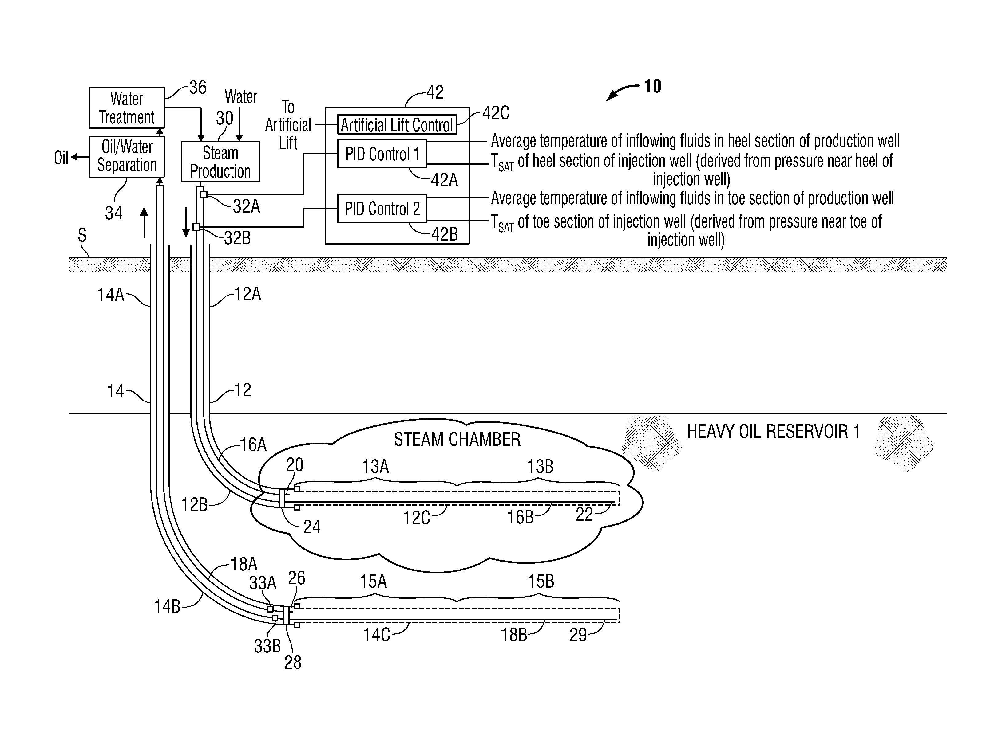
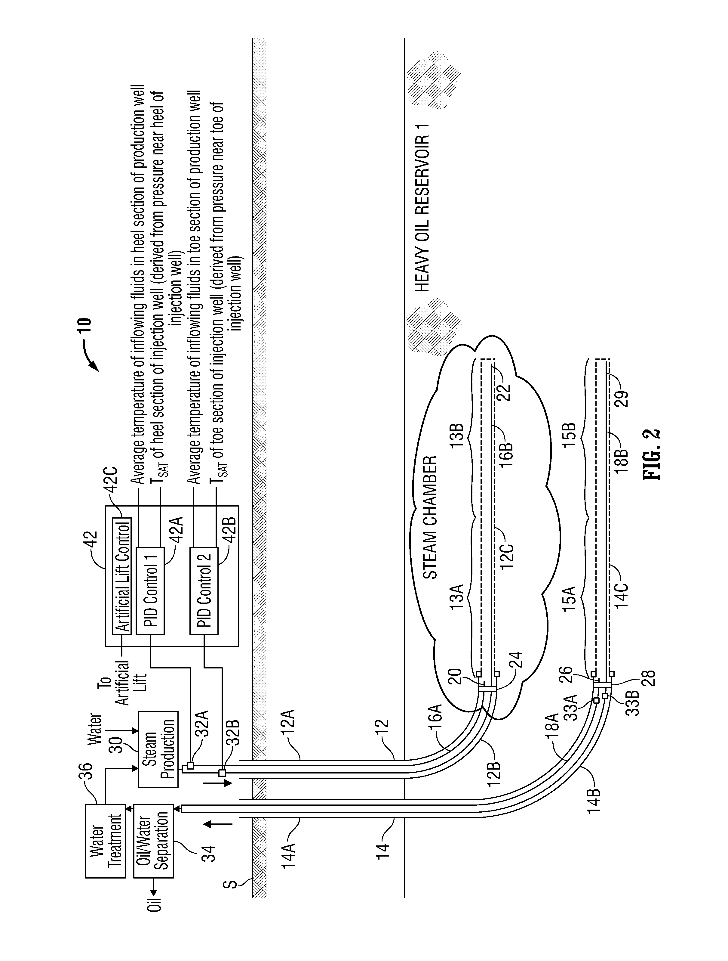
[0034]Turning to FIG. 2, there is shown a schematic diagram of an illustrative embodiment of a SAGD system 10 for producing hydrocarbons from a subterranean heavy oil reservoir 1. The system 10 includes an injection well 12 with a vertical portion 12A, a curved portion 12B, and a “horizontal” portion 12C. In all following discussion, “horizontal” refers to a portion of the well that is approximately horizontal but, in reality, undulates with an axial angular deviation that may be as high as +−5 degrees. It also includes a production well 14 with a vertical portion 14A, a curved portion 14B, and a horizontal portion 14C. Both the curved portion 14B and the horizontal portion 1...


PUM


Abstract

System and method for producing fluids from a hydrocarbon reservoir where an injector well segment and parallel underlying producer well segment are both completed with slotted liners. The injector and producer segments are logically partitioned into corresponding sections to define a plurality of injector-producer section pairs. Injection tubing strings supply stimulating fluid (e.g., saturated steam) to associated sections of the injector segment for injection into the hydrocarbon reservoir. Surface-located control devices control the pressure of the stimulating fluid flowing through the respective injection tubing strings. Production tubing strings (with the aid of artificial lift) carry fluids produced from associated sections of the producer segment. A plurality of controllers is provided for the injector-producer section pairs to control at least one process variable (e.g., interwell subcool temperature) associated with respective injector-producer section pairs over time by adjusting control variables that dictate operation of the control devices for the injection tubing strings.

Description

BACKGROUND[0001]1. Field[0002]The present application relates broadly to systems and methods of hydrocarbon recovery employing an injection well to inject fluids into a subterranean formation and a production well to produce hydrocarbons from the subterranean formation. More particularly, the present application relates to such systems and methods where the injection well and the production well employ multiple tubing strings.[0003]2. Description of Related Art[0004]There are many petroleum-bearing formations from which oil cannot be recovered by conventional means because the oil is so viscous that it will not flow from the formation to a conventional oil well. Examples of such formations are the bitumen deposits in Canada and the United States and the heavy oil deposits in Canada, the United States, and Venezuela. In these deposits, the oil is so viscous under the prevailing temperatures and pressures within the formations that it flows very slowly (or not at all) in response to t...

Claims


Application Information

Patent Timeline
Patent Type & Authority Applications(United States)
IPC IPC(8): E21B43/24E21B44/00
CPCE21B44/00E21B43/2408E21B43/12E21B43/2406
Inventor STONE, TERRY WAYNEBROWN, GEORGE A.
Owner SCHLUMBERGER TECH CORP
Learn More