Liquid crystal composition and liquid crystal display device

a liquid crystal composition and display device technology, applied in the field of liquid crystal composition and liquid crystal display device, can solve the problems of long service life of the device, and achieve the effects of small viscosity, high UV light stability, and large specific resistan

Inactive Publication Date: 2014-06-19
JNC CORP +1
View PDF0 Cites 18 Cited by
  • Summary
  • Abstract
  • Description
  • Claims
  • Application Information

AI Technical Summary

Benefits of technology

[0010]An advantage of the invention is a liquid crystal composition satisfying at least one of characteristics such as a high maximum temperature of a nematic phase, a low minimum temperature of the nematic phase, a small viscosity, a suitable optical anisotropy, a large negative dielectric anisotropy, a low threshold voltage, a large specific resistance, a high stability to ultraviolet light, and a high stability to heat. One aspect of the invention is a liquid crystal composition having a suitable balance regarding at least two of the characteristics. Another aspect is a liquid crystal display device including such a composition. A further aspect is a composition having a suitable optical anisotropy, a large negative dielectric anisotropy and a high stability to ultraviolet light and so forth, and an AM device having a short response time, a large voltage holding ratio, a large contrast ratio, a long service life and so forth.
[0011]Usage of terms herein is as described below. A liquid crystal composition or a liquid crystal display device according to the invention may be occasionally abbreviated as “composition” or “device,” respectively. The liquid crystal display device is a generic term for a liquid crystal display panel and a liquid crystal display module. “Liquid crystal compound” means a compound having a liquid crystal phase such as a nematic phase or a smectic phase, or a compound having no liquid crystal phase but being useful as a component of the composition. Such a useful compound has a six-membered ring such as 1,4-cyclohexylene and 1,4-phenylene, and a rod-like molecular structure. An optically active compound and a polymerizable compound may be occasionally added to the composition. Even in the case where the compounds are liquid crystalline, the compounds are classified as an additive herein. At least one compound selected from the group of compounds represented by formula (1) may be occasionally abbreviated as “compound (1).”“Compound (1)” means one compound or two or more compounds represented by formula (1). A same rule applies to any other compound represented by any other formula. An expression “at least one” in the context of “replaced” shows that not only a position but also the number can be freely selected.
[0012]A higher limit of a temperature range of the nematic phase may be abbreviated as “maximum temperature.” A lower limit of...

Problems solved by technology

A large absolute value of dielectric anisotropy in the composition contributes to a low threshold voltage, a small electric po...

Method used


Image

  • Liquid crystal composition and liquid crystal display device
  • Liquid crystal composition and liquid crystal display device
  • Liquid crystal composition and liquid crystal display device

Examples


example 1

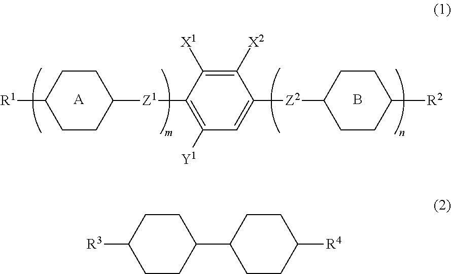
[0139]Among types of compound (1-1-1), a compound as described below was manufactured.

[0140]A phase transition temperature was C 47.5 I. Moreover, the compound was mixed with mother liquid crystals, and values of characteristics of the compound were obtained according to an extrapolation method as follows: NI=−30.7° C.; Δn=0.053.

[0141]1HNMR (CDCl3) (σ): 6.83 (ddd, J=8.5, 8.2, 2.4 Hz, 1H), 6.67 (ddd, J=8.5, 8.2, 1.9 Hz, 1H), 4.53 (dt, J=47.4, 6.1, 2H), 4.09 (q, J=7.0 Hz, 2H), 2.76 (tt, J=12.2, 3.3 Hz, 1H), 1.92-1.85 (m, 4H), 1.65 (ddt, J=26.5, 6.4, 6.1 Hz, 2H), 1.57-1.42 (m, 3H), 1.43 (t, J=7.0 Hz, 3H), 1.15 (dddd, J=13.0, 12.9, 12.2, 3.3 Hz, 2H).

[0142]19FNMR (CDCl3) (σ): −143.82 (dd, J=19.7, 8.2 Hz, 1F), −160.15 (ddd, J=−19.7, 8.2, 2.4 Hz, 1F), −218.63 (tt, J=47.4, 26.5 Hz, 1F).

example 2

[0143]Among types of compound (1-1-1), a compound as described below was manufactured.

[0144]A phase transition temperature was C 58.8 I. Moreover, the compound was mixed with mother liquid crystals, and values of characteristics of the compound were obtained according to an extrapolation method as follows: NI=4.6° C.; Δ∈=−6.8; Δn=0.074.

[0145]1HNMR (CDCl3) (σ): 6.83 (ddd, J=8.4, 8.2, 2.6 Hz, 1H), 6.66 (ddd, J=8.3, 8.2, 1.9 Hz, 1H), 4.45 (dt, J=47.4, 6.3 Hz, 2H), 4.09 (q, J=7.0 Hz, 2H), 2.75 (tt, J=12.2, 3.0 Hz, 1H), 1.88-1.86 (m, 4H), 1.79-1.68 (m, 2H), 1.49-1.40 (m, 2H), 1.43 (t, J=7.0 Hz, 3H), 1.10 (dddd, J=12.7, 12.4, 12.2, 2.9 Hz, 2H).

[0146]19FNMR (CDCl3) (σ): −143.77 (dd, J=19.7, 8.4 Hz, 1F), −160.15 (ddd, J=19.7, 8.3, 2.6 Hz, 1F), −218.23 (tt, J=47.4, 12.2 Hz, 1F).

example 3

[0147]Among types of compound (1-3-1), a compound as described below was manufactured.

[0148]A phase transition temperature was C 89.8 N 183.8 I. Moreover, the compound was mixed with mother liquid crystals, and values of characteristics of the compound were obtained according to an extrapolation method as follows: NI=150.6° C.; Δ∈=−6.2; Δn=0.114; η=51.4 mPa·s.

[0149]1HNMR (CDCl3) (σ): 6.83 (ddd, J=8.2, 7.7, 2.2 Hz, 1H), 6.66 (ddd, J=8.2, 8.1, 1.9 Hz, 1H), 4.43 (dt, J=47.5, 6.3 Hz, 2H), 2.72 (tt, J=12.2, 3.1 Hz, 1H), 1.88-1.65 (m, 10H), 1.44-1.37 (m, 2H), 1.43 (t, J=7.0, 3H), 1.30-1.25 (m, 2H), 1.20-0.86 (m, 9H).

[0150]19FNMR (CDCl3) (a): −143.83 (dd, J=19.7, 7.7 Hz, 1F), −160.21 (ddd, J=19.7, 8.1, 2.2 Hz, 1F), −218.06 (tt, J=47.5, 24.4 Hz, 1F).


PUM

PropertyMeasurementUnit
Temperatureaaaaaaaaaa
Nanoscale particle sizeaaaaaaaaaa

Abstract

A liquid crystal composition and an AM liquid crystal display device are described. The liquid crystal composition has a negative dielectric anisotropy, contains a specific compound having a large negative dielectric anisotropy as a first component and a two-ring compound having a small viscosity as a second component, and may further contain a specific compound having a large negative dielectric anisotropy as a third component, a specific compound having a small viscosity as a fourth component and a specific compound having a large negative dielectric anisotropy as a fifth component. The AM liquid crystal display device includes the liquid crystal composition.

Description

TECHNICAL FIELD[0001]The invention relates to a liquid crystal composition mainly suitable for use in an active matrix (AM) device and so forth, and an AM device and so forth containing the composition. More specifically, the invention relates to a liquid crystal composition having a negative dielectric anisotropy, and a device that includes the composition and has a mode such as an in-plane switching (IPS) mode, a vertical alignment (VA) mode, a fringe field switching (FFS) mode, a polymer sustained alignment (PSA) mode, or a field induced photo-reactive alignment (FPA) mode.BACKGROUND ART[0002]In a liquid crystal display device, a classification based on an operating mode for liquid crystals includes a phase change (PC) mode, a twisted nematic (TN) mode, a super twisted nematic (STN) mode, an electrically controlled birefringence (ECB) mode, an optically compensated bend (OCB) mode, an in-plane switching (IPS) mode, a vertical alignment (VA) mode, a fringe field switching (FFS) mo...

Claims


Application Information

Patent Timeline
IPC IPC(8): C09K19/34C09K19/30C09K19/32
CPCC09K19/12C09K19/3003C09K19/3066C09K19/3068C09K19/3402C09K2019/0407C09K2019/122C09K2019/3009C09K2019/301C09K2019/3016C09K2019/3422C09K2019/3425C09K2323/00G02F1/0045G02F1/13712C09K19/32G02F1/13
Inventor GOTO, YASUYUKISAIGUSA, KAZUHIKOHATTORI, NORIKATSU
Owner JNC CORP
Why Eureka
Try Eureka