Generator control system for smooth operation with combusion engine

a technology of combusion engine and control system, which is applied in the direction of electric vehicle, battery/cell propulsion, electrical apparatus, etc., can solve the problems of increasing torque at the generator shaft and increasing pressure in the cylinder

Inactive Publication Date: 2014-06-19
FEV
View PDF13 Cites 3 Cited by
  • Summary
  • Abstract
  • Description
  • Claims
  • Application Information

AI Technical Summary

Benefits of technology

[0021]Subsequently, the control system of the control unit which controls the generator is depicted as generator control system. Said generator control system has the effect that during the compression phase or during an entire operation cycle of each cylinder of the combustion engine the crankshaft gear remains in constant contact with the generator shaft gear. The crankshaft gear comprises crankshaft gear sprockets with front gear tooth flanks oriented in rotational direction of the crankshaft. In the same manner, the generator shaft gear comprises generator shaft gear sprockets with a rear gear tooth flank oriented opposite to the rotational direction of the generator shaft. The generator control system is designed in such a way that during the compression phase or during an entire operation cycle of each cylinder of the combustion engine the crankshaft gear has only permanent contact with the generator shaft gear by one or several front gear tooth flanks of the crankshaft gear and by one or several rear gear tooth flanks of the generator shaft gear. This permanent contact between the crankshaft gear and the generator shaft gear has the effect that no contact alterations or tooth flank changes occurs between the crankshaft gear and the generator shaft gear during the compression phase or during the entire operation cycle of each cylinder of the combustion engine.

Problems solved by technology

In particular, the start of combustion in a cylinder results in an increase of pressure in the cylinder, as well as a torque increase at the generator shaft.

Method used


Image

  • Generator control system for smooth operation with combusion engine
  • Generator control system for smooth operation with combusion engine
  • Generator control system for smooth operation with combusion engine

Examples


Embodiment Construction

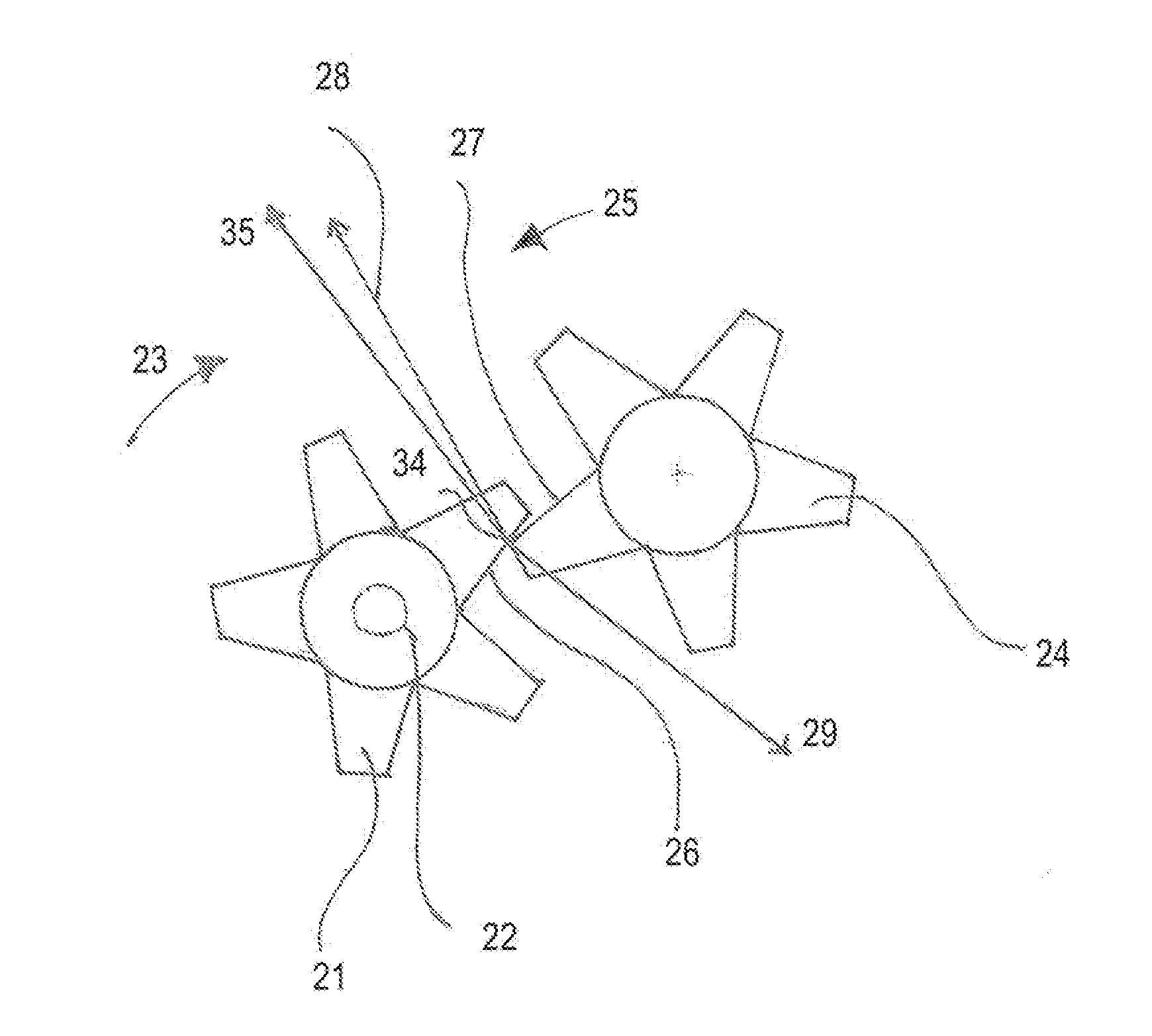
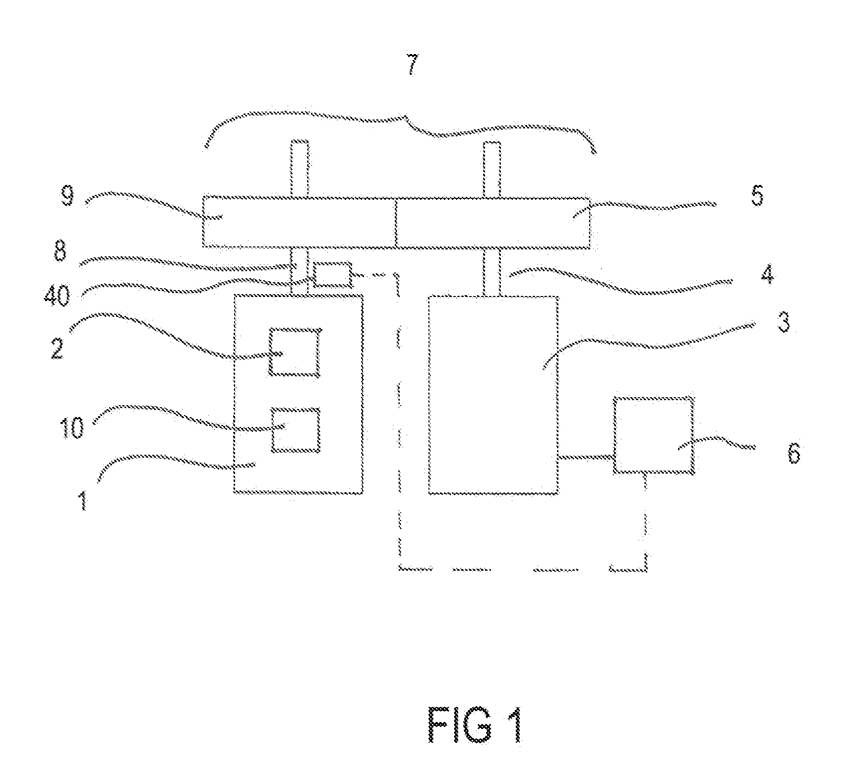
[0061]FIG. 1 shows a combustion engine 1 with a first cylinder 2 and a second cylinder 10. FIG. 1 also shows a generator 3 with a generator shaft 4, which has a generator shaft gear 5 and a control unit 6, which control at least the generator 3, and a rotational connection 7. Via the generator shaft gear 5, the crankshaft 8 is connected with the generator shaft 4 by a crankshaft gear 9. The control unit 6 controls the generator 3 in such a way that during the operation of the combustion engine 1 the crankshaft gear 9 is permanently engaged with the generator shaft gear 5. Preferably, the permanent contact between the crankshaft gear 9 and the generator shaft gear 5 is achieved in that the control device 6 controls the generator in such a way that during the compression stroke a conversion torque is generated within the generator when the combustion engine is operating. Said conversion torque has a decelerating effect on the generator shaft 4 and, via the generator shaft gear 5 and t...


PUM


Abstract

A combustion engine comprising at least a cylinder, a generator having a generator shaft with a generator shaft gear, a crankshaft having a crankshaft gear and a control unit, which controls at least the generator in such a way that it is possible to avoid a tooth flank change between the generator shaft gear and the crankshaft gear during an entire combustion cycle of the combustion engine.

Description

CROSS-REFERENCE TO RELATED APPLICATIONS[0001]The disclosure of German Patent Application DE 10 2012 024 551.3 filed on Dec. 17, 2012, including the specification, drawings, and abstract, is incorporated herein by reference in its entirety.FIELD OF THE INVENTION[0002]The invention relates to a combustion engine comprising at least one cylinder, a generator having a generator shaft with a generator shaft gear, a control unit which controls at least the generator, and a rotational connection which connects a crankshaft having a crankshaft gear of the combustion engine with the generator shaft. In the process, the generator shaft rotates in the opposite direction of the crankshaft and is arranged in parallel fashion to the crankshaft. The products of moments of inertia and the respectively associated speed ratios of individual rotary components rotationally coupled by means of the rotational connection cancel each other out at least approximately.BACKGROUND OF THE INVENTION[0003]Combust...

Claims


Application Information

Patent Timeline
Patent Type & Authority Applications(United States)
IPC IPC(8): H02P9/04
CPCH02P9/04H02P9/008B60L2240/423B60L2240/441B60L2270/142B60L50/61Y02T10/62Y02T10/64Y02T10/70Y02T10/7072
Inventor PISCHINGER, MARTINANDERT, JAKOB
Owner FEV
Why Eureka
Try Eureka