
Capacitive rotary encoder

Active Publication Date: 2014-06-19
PANASONIC AUTOMOTIVE SYST OF AMERICA
View PDF6 Cites 77 Cited by
  • Summary
  • Abstract
  • Description
  • Claims
  • Application Information

AI Technical Summary

Benefits of technology

The present invention has two main advantages: the touch screen can be re-programmed and the benefits of a rotary dial are retained, such as tactile feedback and a fixed dial location that helps with muscle memory. Additionally, the invention provides a well-defined area for capturing and recognizing hand gestures through a camera and gesture recognition algorithm.

Problems solved by technology

Current systems require discrete rotary encoders and additional support circuitry attached to a printed circuit board, and are not able to be located over the active display area without obstructing the display from view.
This not only occupies valuable display area, but also limits design freedom and the ability to dynamically assign and label the control function.
However, these known approaches have significantly higher costs than the present invention, and have yet to be automotive qualified.

Method used


Image

  • Capacitive rotary encoder
  • Capacitive rotary encoder
  • Capacitive rotary encoder

Examples


Embodiment Construction

[0019]The embodiments hereinafter disclosed are not intended to be exhaustive or limit the invention to the precise forms disclosed in the following description. Rather the embodiments are chosen and described so that others skilled in the art may utilize its teachings.

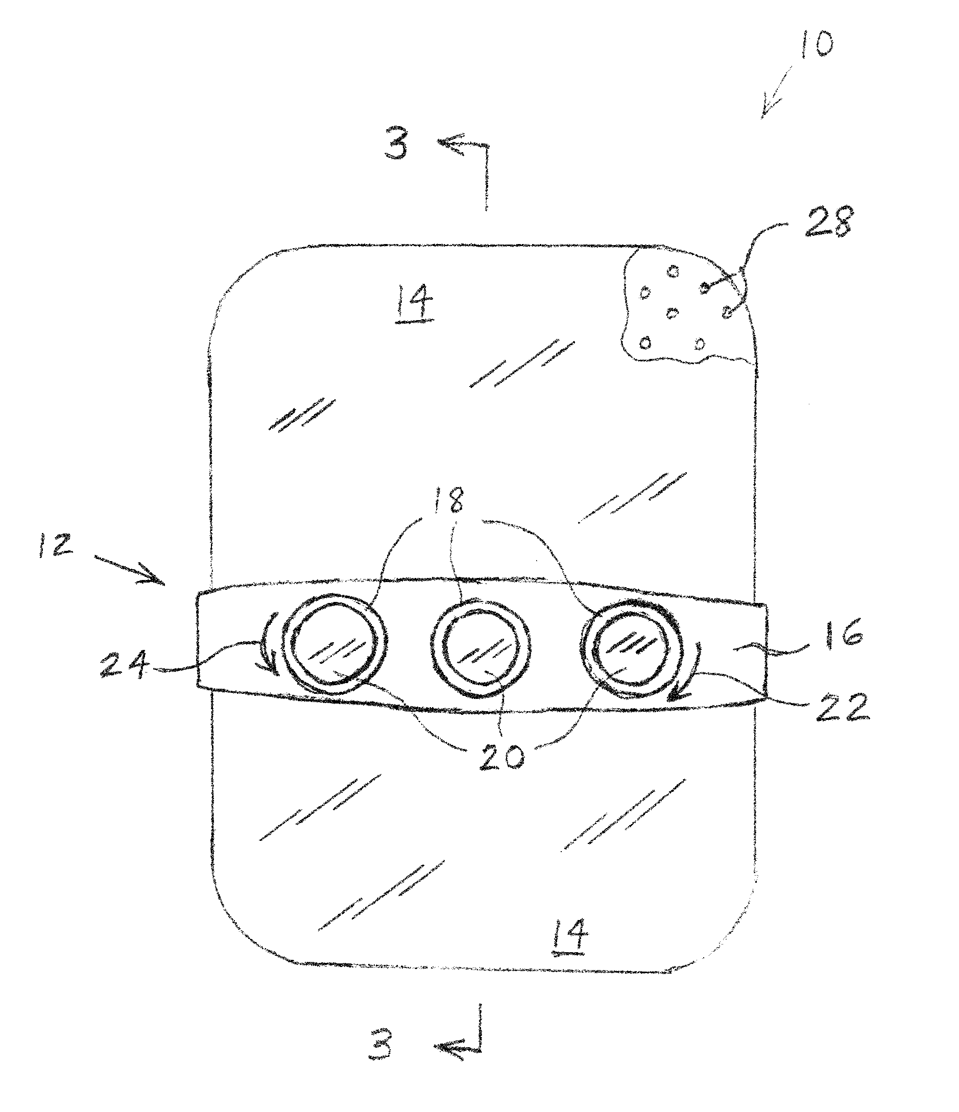
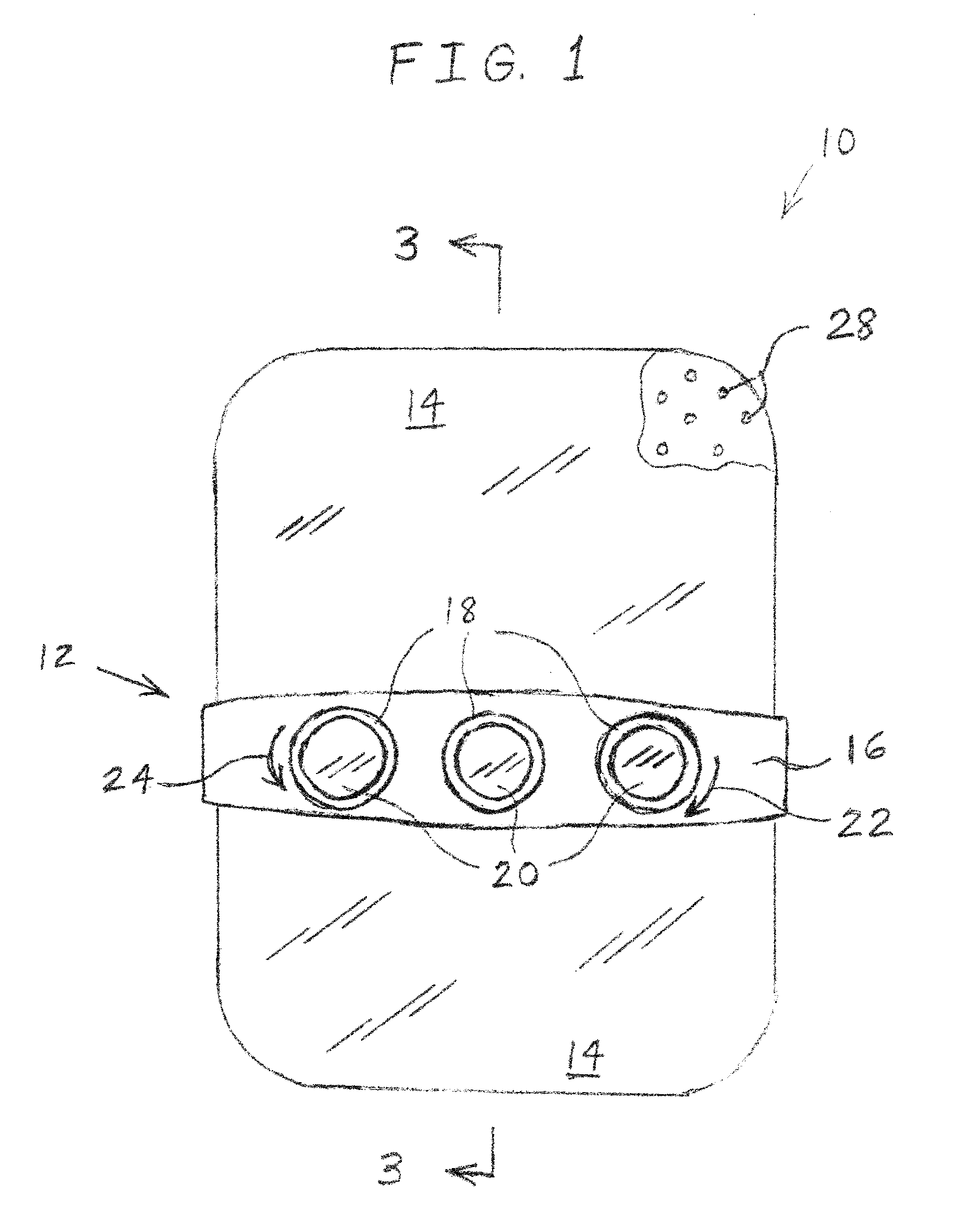
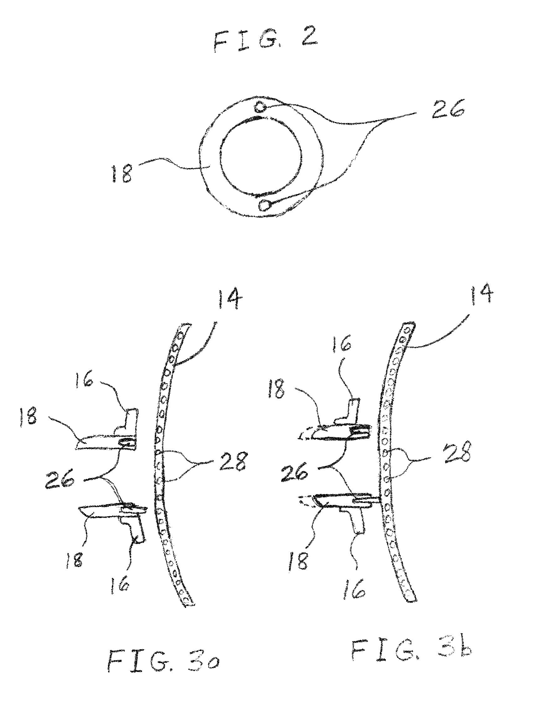
[0020]FIG. 1 is a block diagram illustrating one embodiment of a human machine interface in the form of a capacitive rotary encoder arrangement 10 of the present invention, which may be included in a motor vehicle, for example. Arrangement 10 includes a rotary control overlay 12 disposed over, or superimposed over, a capacitive touch screen 14. Overlay 12 includes a planar band 16 having opposite longitudinal ends attached to screen 14. Band 16 may be a fixed structure that is formed of metal or a rigid plastic material, for example. Band 16 includes three throughholes each of which receives a respective annular capacitive rotary encoder or control device in the form of a dial or knob 18 that is rotatably coupled to b...


PUM


Abstract

A human machine interface includes a capacitive touch screen having a capacitive sensor. The capacitive touch screen displays text characters and / or graphical information. A control device is rotatably coupled to a structure such that the control device is superimposed over the screen. The control device includes at least one electrically conductive element. The control device rotates about an axis substantially perpendicular to the screen such that the at least one electrically conductive element follows the rotation of the control device. The capacitive sensor senses a rotational position of the at least one electrically conductive element.

Description

BACKGROUND OF THE INVENTION[0001]1. Field of the Invention[0002]The present invention relates to capacitive touch screens, and, more particularly, to a control device that is applied to a capacitive touch screen.[0003]2. Description of the Related Art[0004]Current systems require discrete rotary encoders and additional support circuitry attached to a printed circuit board, and are not able to be located over the active display area without obstructing the display from view. This not only occupies valuable display area, but also limits design freedom and the ability to dynamically assign and label the control function.[0005]Other inventions targeted toward the automotive industry include projection type displays and camera-based pattern recognition to decode the controls which have been overlaid on the display surface. However, these known approaches have significantly higher costs than the present invention, and have yet to be automotive qualified.SUMMARY OF THE INVENTION[0006]The i...

Claims


Application Information

Patent Timeline
IPC IPC(8): G06F3/044
CPCG06F3/044G06F3/0362G06F3/0393B60K35/10B60K2360/145B60K2360/126B60K2360/143G06F3/016G06T11/60
Inventor GRAIG, LARRY V.KOBAYASHI, SACHIKO KUROKAWA
Owner PANASONIC AUTOMOTIVE SYST OF AMERICA
Learn More