Light-emitting element, light-emitting device, and method for producing light-emitting element

Active Publication Date: 2014-06-19
SHARP FUKUYAMA LASER CO LTD
View PDF2 Cites 57 Cited by
  • Summary
  • Abstract
  • Description
  • Claims
  • Application Information

AI Technical Summary

Benefits of technology

[0028]According to the above method, it is possible to produce a light-emitting element which can satisfy eye safety requirements by enhancing efficiency in enlarging the light-emission spot size of the laser light that reaches the light-emitting section and can increase a degree of freedom in designing the element as a whole.
[0029]The light-emitting element according to the present invention includes a light-emitting section which is irradiated with the laser light and generates the fluorescent light and a transparent member which is provided on a laser light irradiation si

Problems solved by technology

However, since the film thickness of the diffusing layer is significantly thin compared to the circular substrate with no diffusing function in the light-emitting wheel disclosed in PTL 1, there is a problem that efficiency in increasing the light-emission spot size of the laser light while passing through the circular substrate and the diffusing layer until the laser light reaches the phosphor is low and that eye safety cannot be satisfied in practice.
In contrast, since lase

Method used


Image

  • Light-emitting element, light-emitting device, and method for producing light-emitting element
  • Light-emitting element, light-emitting device, and method for producing light-emitting element
  • Light-emitting element, light-emitting device, and method for producing light-emitting element

Examples


Embodiment Construction

[0049]A description will be given of an embodiment of the present invention based on FIGS. 1 to 15 as follows. Although descriptions of configurations other than the configurations described in the following specific sections are omitted in some cases, the configurations whose descriptions are omitted are the same as those described in other sections. Same reference numerals are assigned to members with the same functions as those of members illustrated in the respective sections for convenience of explanation, and descriptions thereof will be appropriately omitted.

[1. Configuration of Light-Emitting Element 10a]

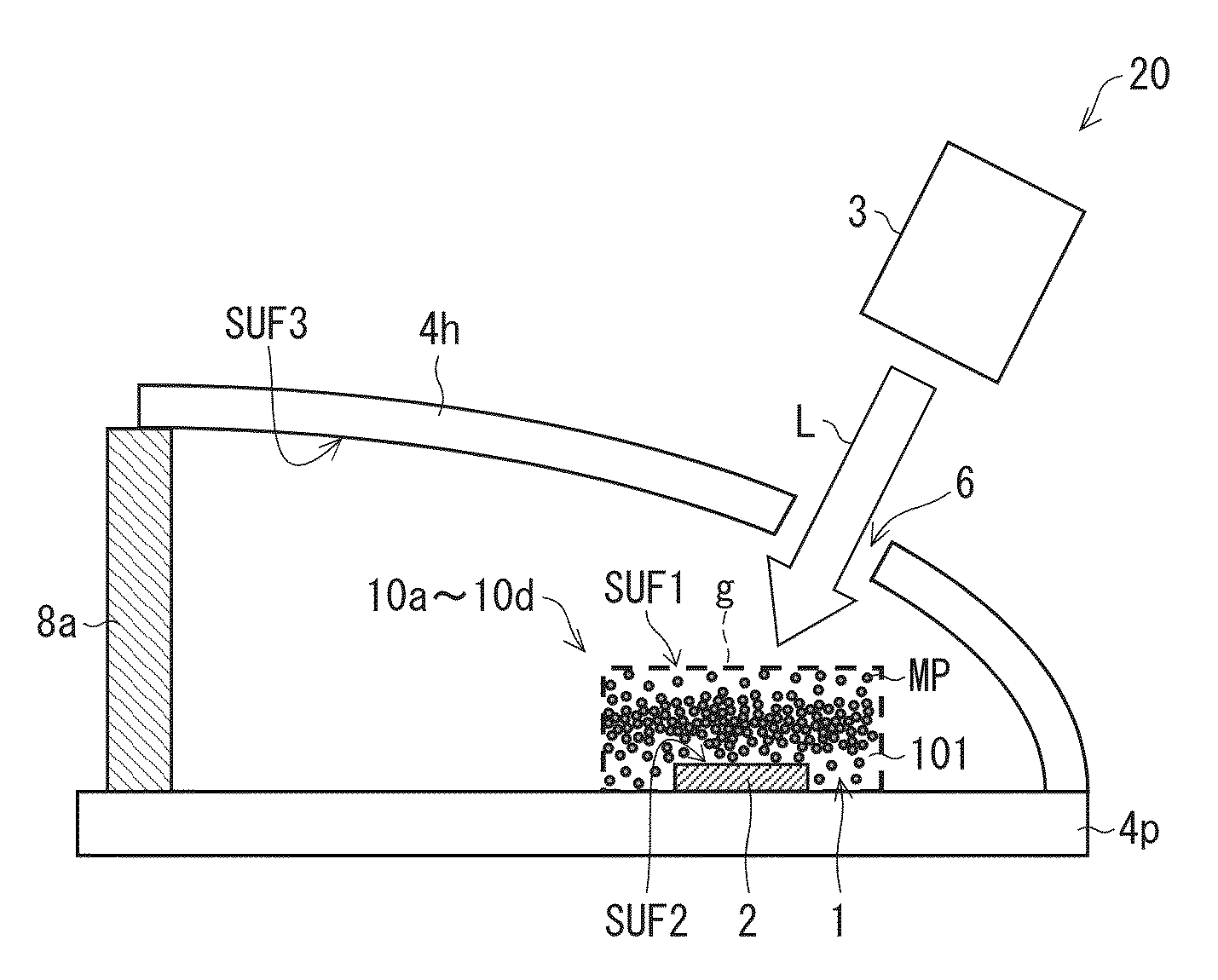
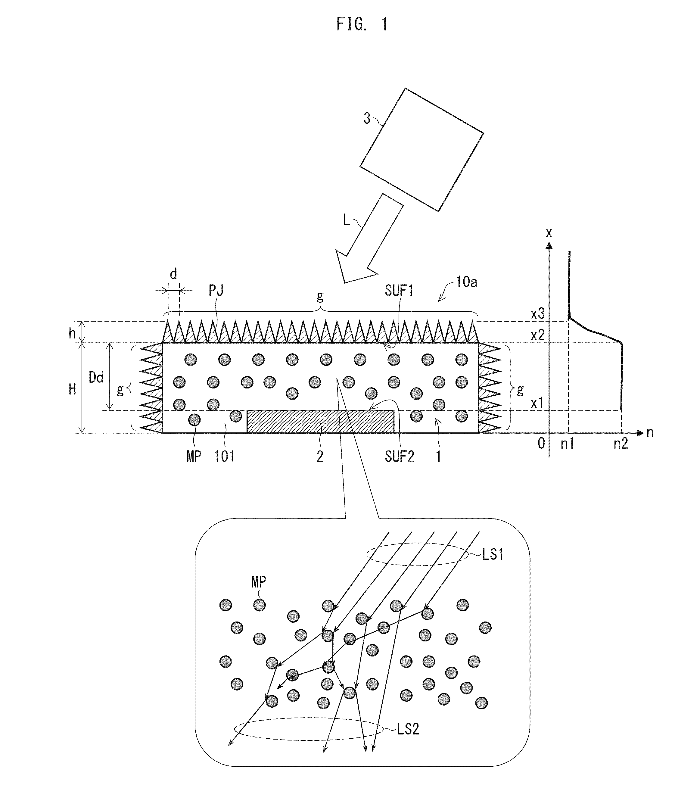
[0050]First, a description will be given of a configuration of a light-emitting element 10a according to an embodiment of the present invention based on FIG. 1. In addition, FIG. 1 is a cross-sectional view schematically illustrating the configuration of the light-emitting element 10a, and actual dimensions of the respective constituents are not reflected.

[0051]As illustrate...


PUM

PropertyMeasurementUnit
Thicknessaaaaaaaaaa
Diameteraaaaaaaaaa
Densityaaaaaaaaaa

Abstract

A light-emitting section (2) and a transparent member (1) which is arranged on a side of a surface (SUF2) of the light-emitting section (2) and exhibits transparency with respect to laser light (L) are provided, and the transparent member (1) includes a plurality of scattering microregions (MP) which isotropically scatter the laser light (L) passing therethrough and increase a light-emission spot size of the laser light (L).

Description

REFERENCE TO RELATED APPLICATIONS[0001]This application is a national stage application under 35 USC 371 of International Application No. PCT / JP2012 / 067135, filed Jul. 4, 2012, which claims the priority of Japanese Patent Application No. 2011-167739, filed Jul. 29, 2011, the entire contents of which are incorporated herein by reference.FIELD OF THE INVENTION[0002]The present invention relates to a light-emitting element provided with a phosphor (light-emitting section) which generates fluorescent light by irradiation with laser light, a light-emitting device provided with the light-emitting element, and a method for producing the light-emitting element.BACKGROUND OF THE INVENTION[0003]In recent years, light-emitting devices configured to employ solid light-emitting elements such as light emitting diodes (LED) or semiconductor lasers (LD; Laser Diodes) as excitation light sources and use, as illumination light, fluorescent light generated by irradiating a light-emitting section, whic...

Claims


Application Information

Patent Timeline
IPC IPC(8): F21K99/00
CPCG02B5/0242G02B5/0278G02B5/045F21Y2115/30F21Y2115/10F21S41/16Y10T29/49002F21K9/64F21K9/90F21V13/14F21V9/38F21S41/176
Inventor KISHIMOTO, KATSUHIKOSATO, RINAKAWANISHI, HIDENORI
Owner SHARP FUKUYAMA LASER CO LTD
Why Eureka
Try Eureka