Lamp reflector

a technology of reflector and reflector body, which is applied in the direction of reflector, lighting device details, lighting apparatus, etc., can solve the problems of numerous segments remaining radially movable inward, prone to deformation, and difficult mounting, etc., and achieves a larger diffusion effect and small width

Inactive Publication Date: 2014-06-19
JORDAN REFLEKTOREN
View PDF3 Cites 7 Cited by
  • Summary
  • Abstract
  • Description
  • Claims
  • Application Information

AI Technical Summary

Benefits of technology

[0012]According to the present invention, it can further be convenient, if the holding ring has a width on its contact side, which is greater than/equal to the width of the flange rim. By arranging the holding ring on the visible side of the flange rim, the slots in the region of the flange are completely covered. By arranging the holding ring on the rear side of the flange rim, the holding ring can also have a smaller width than the flange rim.
[0013]According to the present invention, it is in particular advantageous if the base section and the light exit opening are coaxially arranged relative to the longitudinal axis and lie on a perpendicular plane relative to it, an opening for luminaries being conveniently configured on the base section through which the luminaries can be inserted. The light exit opening as well as the opening for luminaries is preferentially executed as a circular opening. In this case, it is also particularly advantageous, if the flange rim runs on a plane perpendicular to the longitudinal axis, and, in particular, has an inner and outer circular peripheral contour. In this case, it is likewise an advantage if the holding ring has an inner and outer circular peripheral contour. It is further convenient, if the reflector body is shaped rotationally symmetrical to the longitudinal axis, the peripheral wall having a paraboloid shape in the longitudinal section in a plane passing through the center axis from the base section to the light exit opening, so that the reflector body has the shape of a rotational paraboloid. The reflector body is conveniently formed from a one-piece, flat material blank having a thickness from greater than/equal to 0.2 mm to less than/equal to 1 mm, in particular 0.5 mm. In this case, the reflector body is preferentially made by stamping and mechanical forming. The holding ring is conveniently formed from a flat material blank having a thickness from greater than/equal to 0.2 mm and less than/equal to 1 mm, in particular 0.5 mm. Aluminum is preferentially used as a material for manufacturing the reflector body as well as for manufacturing the holding ring. It is lik

Problems solved by technology

The disadvantage here is that the reflector has recesses in the region of its reflective surface through which the catch projections of the ring are visible.
In addition, the individual segments or “fingers” are only in part secured to the ring; depending o

Method used


Image

  • Lamp reflector
  • Lamp reflector
  • Lamp reflector

Examples


Embodiment Construction

[0025]With respect to the following description, it is explicitly stated that the invention is not restricted to the exemplary embodiments, and thus not to all or several characteristics of the described combinations of characteristics; rather, any individual partial characteristic of the / of any exemplary embodiment can also be considered as having inventive importance, also independently of all other partial characteristics described in connection therewith, alone and also in combination with any characteristics of another exemplary embodiment, as well as independently of the combinations of characteristics and retroactive application of the claims.

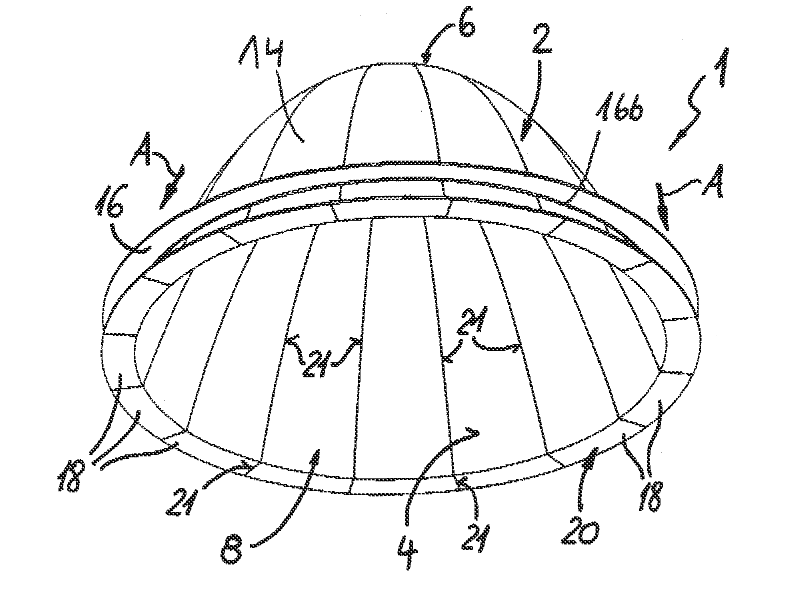
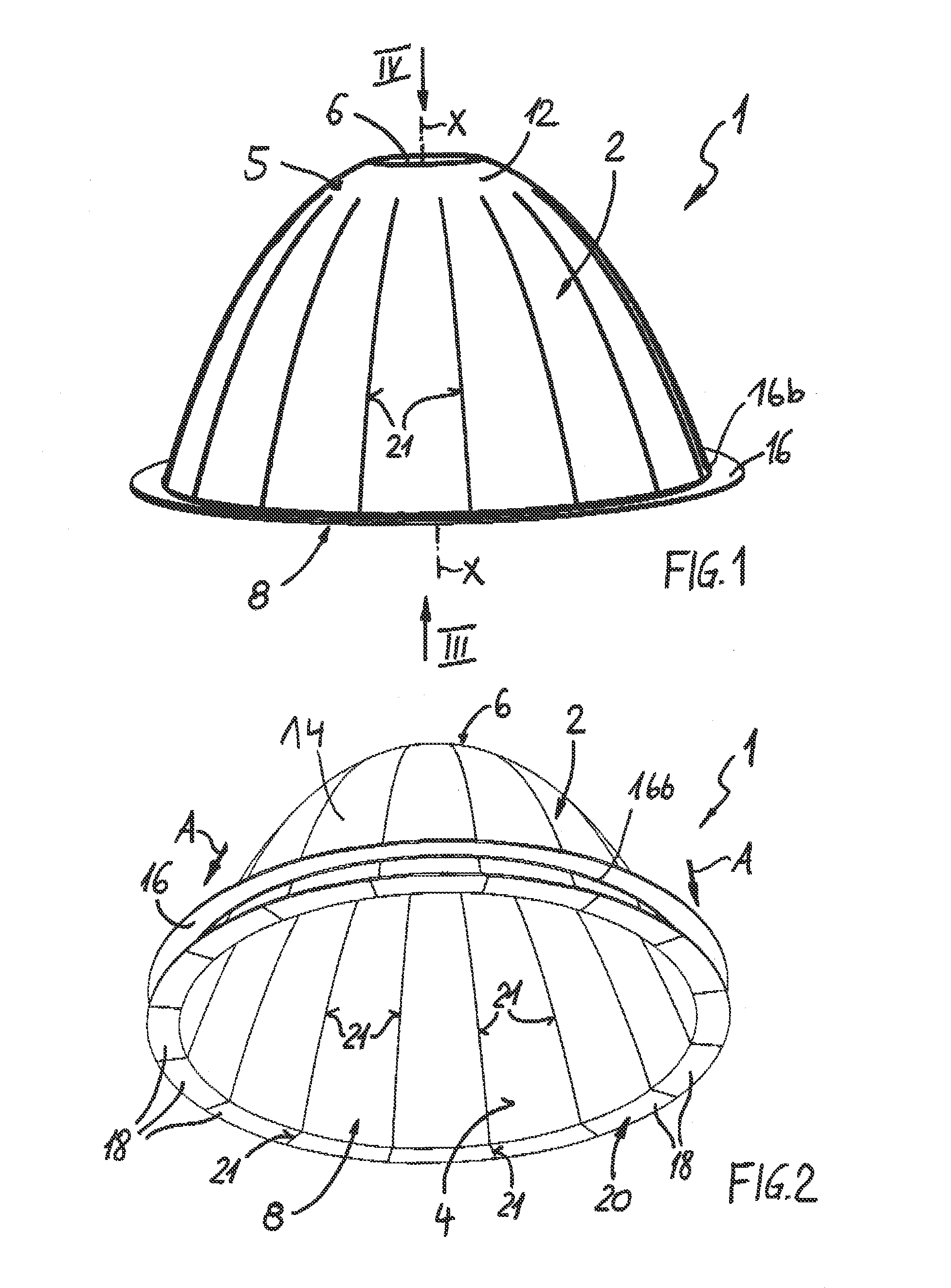
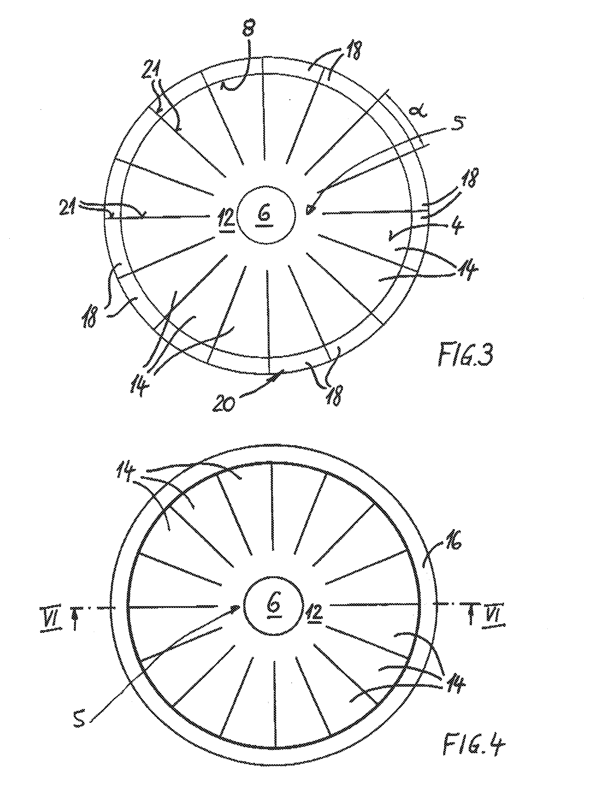
[0026]As is apparent from FIG. 1, a lamp reflector 1 according to the present invention consists of a reflector body 2, whose peripheral wall has a lateral surface of a geometrical body with a longitudinal axis X-X, the reflector body 2 having the shape of a rotational paraboloid in the shown exemplary embodiment. It can, however, likewi...


PUM

PropertyMeasurementUnit
Thicknessaaaaaaaaaa
Thicknessaaaaaaaaaa
Thicknessaaaaaaaaaa

Abstract

A lamp reflector having a reflector body enclosing an inner space, whose peripheral wall forms a lateral surface of a geometrical body with a longitudinal axis. The reflector body has a light exit opening and a base section opposite thereto. The peripheral wall is formed by a wall section forming the base section, and, extending therefrom in the direction of the light exit opening, by circumferential adjacent segments that are separated by slots. The segments are secured to the perimeter of the reflector body via a holding ring that encloses it. On their free ends, the segments have outward angled flange sections that jointly form a circumferential flange rim. In its mounting position, the holding ring is adjacent to the flange rim and is at least force-fitted to the flange rim.

Description

CROSS REFERENCE TO RELATED APPLICATIONS[0001]This application claims priority to U.S. Provisional Patent Application No. 61 / 811,862 entitled LAMP REFLECTOR, filed on Apr. 15, 2013, which claims priority to German Patent Application No. DE 20 2012 104 901.5, filed on Dec. 17, 2012, the entire contents of which are hereby incorporated by reference.BACKGROUND[0002]1. Field of the Invention[0003]The present invention relates to a lamp reflector having a reflector body enclosing an inner space, whose peripheral wall forms a lateral surface of a geometrical body with a longitudinal axis, the reflector body having a light exit opening, and a base section opposite the light exit opening, the peripheral wall being formed by a wall area that forms the base section, from where circumferentially adjacent segments separated by slots extend in the direction of the light exit opening.[0004]2. Description of Related Art[0005]A reflector of the type to which the present invention relates has been de...

Claims


Application Information

Patent Timeline
IPC IPC(8): F21V7/04
CPCF21V7/048F21V7/10F21V7/24F21V7/28
Inventor MOCKING, ANDREASLAFTSIDIS, IOANNISELFMANN, KAI
Owner JORDAN REFLEKTOREN
Why Eureka
Try Eureka