Engine stop control device for hybrid vehicle

Active Publication Date: 2014-06-19
TOYOTA JIDOSHA KK
View PDF15 Cites 24 Cited by
  • Summary
  • Abstract
  • Description
  • Claims
  • Application Information

AI Technical Summary

Benefits of technology

The engine stop control device for hybrid vehicles described in this patent allows for proper ignition start and reduces assist torque at the time of engine start. It achieves this by automatically stopping the crankshaft at a crank angle associated with low pumping energy when the crankshaft is near the compression TDC (top dead center) during engine stop or immediately after engine stop. This is done by connecting the clutch, which is temporarily connected at the time of engine stop or afterward, to the crankshaft and rotating it to a target stop range. The connection process of the clutch is executed within a time when pumping action due to compression of air in the cylinder is acquired, and the crankshaft is automatically stopped at a crank angle associated with low pumping energy. This allows for proper ignition start and reduces assist torque at the time of engine start.

Problems solved by technology

However, in Cited Document 1, since the clutch is simply connected (frictionally engaged) for a constant time during stop of the direct injection engine to rotate the crankshaft, the crank angle cannot promptly be put into a predetermined range and may not be in time for engine start.
In Cited Document 2, a stop position of the crankshaft is adjusted by a rotation load of the alternator; however, in the case of a hybrid vehicle having the direct injection engine connected / disconnected to / from a power transmission path by the clutch, the connection of the clutch only rotates the crankshaft such that differential rotation becomes smaller, and cannot put a brake and, therefore, the technique described in Cited Document 2 is not applicable to the hybrid vehicle described in Cited Document 1 for adjusting the crank angle during engine stop.
If a crankshaft stops near the compression TDC, in the case of an eight-cylinder engine, since the previous cylinder in the vicinity of a crank angle of 90 degrees and is still in the expansion stroke, the ignition start can be achieved; however, an exhaust valve shortly opens to start an exhaust stroke (e.g., near 120 degrees) and, therefore, sufficient rotation energy is not expected and a large assist torque is required at the time of start.
In the case of two- to six-cylinder engines, since the previous cylinder has already passed through the expansion stroke, no cylinder is in the expansion stroke and the ignition start itself is impossible.

Method used


Image

  • Engine stop control device for hybrid vehicle
  • Engine stop control device for hybrid vehicle
  • Engine stop control device for hybrid vehicle

Examples


first example

[0046]An example of the present invention will now be described in detail with reference to drawings.

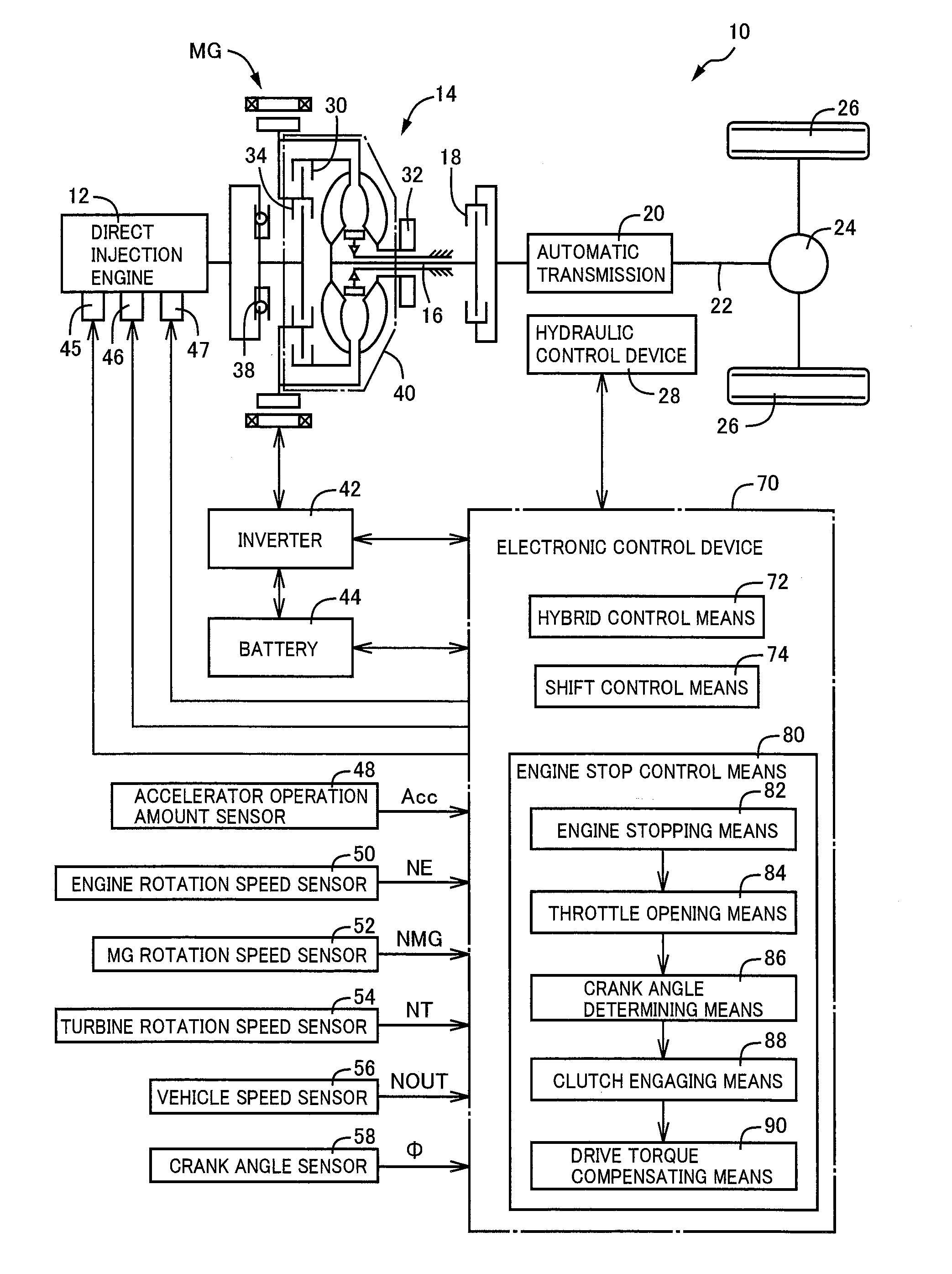
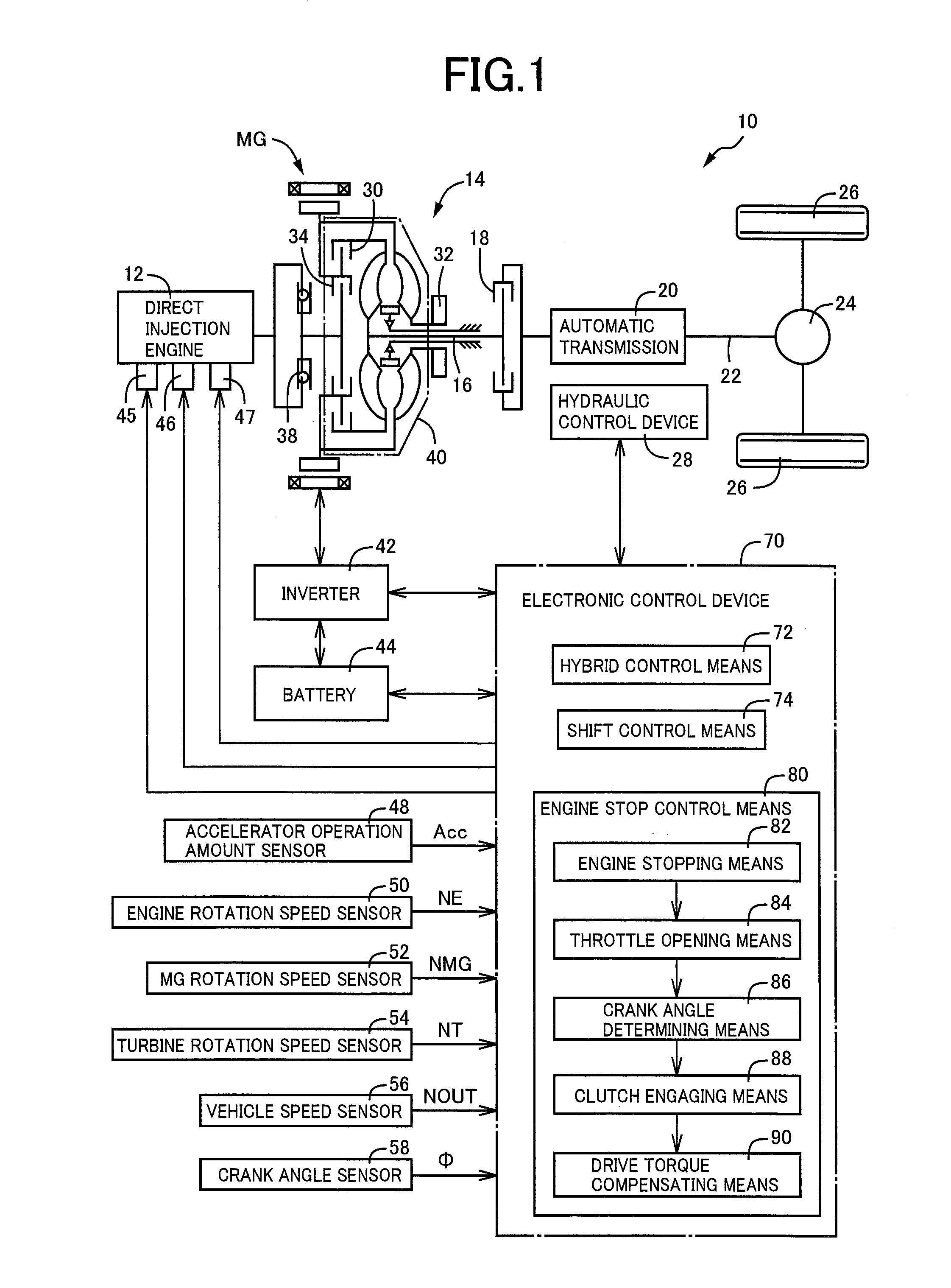
[0047]FIG. 1 is a diagram of a general configuration including a schematic of a drive system of a hybrid vehicle 10 to which the present invention is preferably applied. The hybrid vehicle 10 includes a direct injection engine 12 directly injecting fuel into a cylinder and a motor generator MG acting as an electric motor and an electric generator, as a drive power source for running. An output of the direct injection engine 12 and the motor generator MG is transmitted from a torque converter 14 that is a hydraulic power transmission device via a turbine shaft 16 and a C1 clutch 18 to an automatic transmission 20 and further transmitted via an output shaft 22 and a differential gear device 24 to left and right drive wheels 26. The torque converter 14 includes a lockup clutch (L / U clutch) 30 directly coupling a pump impeller and a turbine impeller with the pump impeller integrally conn...

second example

[0077]Another example of the present invention will be described. In the following description, the portions substantially common with the example are denoted by the same reference numerals and will not be described in detail.

[0078]FIG. 9 is a flowchart used instead of FIG. 4 and a difference exists in a process after determining whether the stop crank angle φstop (including the estimated stop crank angle φest) at the time of stop of rotation of the direct injection engine 12 is within a range of the predefined target stop range φtarget at step R6. In particular, if the stop crank angle φstop is within the range of the target stop range φtarget and the determination of step R6 is YES, an instruction is output for using a standard value as an assist torque for cranking at the next engine start at step R7-1 and, if the stop crank angle φstop is out of the range of the target stop range φtarget and the determination of step R6 is NO, an increment instruction is output for making the as...

third example

[0080]FIG. 10 is a diagram for explaining yet another example and a difference exists in an engagement process of the K0 clutch 34 as compared to the example of FIG. 9. In the examples of FIGS. 4 and 9, it is determined at step R3 whether the crank angle φ falls within the range of the target stop range φtarget, and when the crank angle φ falls within the range of the target stop range φtarget, steps R4 and later are executed; however, in FIG. 10, step R3-1 is provided instead of step R3 to determine whether a predetermined time defined in advance has elapsed and, if the predetermined time has elapsed, steps R4 and later are executed to interrupt the K0 clutch 34. With regard to this predetermined time, on the assumption that the crankshaft 114 is stopped near the compression TDC, a constant time is defined in advance such that the crankshaft 114 can be rotated against the friction etc., into the minimum region of the pumping energy, with consideration given to the K0 clutch pressur...


PUM


Abstract

An engine stop control device of a hybrid vehicle has a direct injection engine directly injecting fuel into a cylinder, a clutch connecting / disconnecting the direct injection engine to / from a power transmission path, and a rotating machine at least acting as an electric motor. The hybrid vehicle uses the direct injection engine and the rotating machine as a drive power source for running, and the once interrupted clutch is temporarily connected at the time of the engine stop or immediately after the engine stop when the clutch is interrupted to stop the direct injection engine during running.

Description

TECHNICAL FIELD[0001]The present invention relates to an engine stop control device of a hybrid vehicle including a direct injection engine.BACKGROUND ART[0002]A hybrid vehicle is known that has (a) a direct injection engine directly injecting fuel into a cylinder, (b) a clutch connecting / disconnecting (coupling / interrupting) the direct injection engine to / from a power transmission path, and (c) a rotating machine at least acting as an electric motor and (d) that can use the direct injection engine and the rotating machine as a drive power source for running. A hybrid vehicle described in Patent Document 1 is an example thereof and, during motor running using only the rotating machine as the drive power source for running, a friction clutch is connected (frictionally engaged) to rotate and adjust a crankshaft of the direct injection engine such that a crank angle in a cylinder in an expansion stroke falls within a predetermined range so as to inject fuel into the cylinder in the exp...

Claims


Application Information

Patent Timeline
IPC IPC(8): B60W20/00B60W10/06B60W10/02B60W10/08B60L50/16
CPCB60W20/00B60W10/02Y10S903/93B60W10/08B60W10/06B60K6/48B60W20/40F02N19/005F02N99/006F02N2019/008B60K2006/4825Y02T10/62B60W2510/0685F16D48/06F16D2500/10412F16D2500/1045F16D2500/1066F16D2500/30401F16D2500/3061F16D2500/3069F16D2500/3166F16D2500/5043F16D2500/7041F16D48/00
Inventor NAKANISHI, NAOKIKATO, YASUYUKIIDESHIO, YUKIHIKOKOJIMA, SUSUMU
Owner TOYOTA JIDOSHA KK
Why Eureka
Try Eureka