Method for detecting combustion noise in internal combustion engine, combustion noise detection device, and device for controlling internal combustion engine

a technology for internal combustion engines and detection devices, applied in the direction of electric control, ignition automatic control, instruments, etc., to achieve the effect of improving detecting the combustion condition with high accuracy, and improving the fuel efficiency performance or/and the emission performance of the internal combustion engin

Active Publication Date: 2014-06-19
HITACHI ASTEMO LTD
View PDF30 Cites 27 Cited by
  • Summary
  • Abstract
  • Description
  • Claims
  • Application Information

AI Technical Summary

Benefits of technology

[0018]According to the present invention, it is possible to detect combustion condition with high accuracy by appropriately selecting a sensed frequency or frequency band of a combustion noise sensor according to a combustion mode. Consequently, the combustion condition of the internal combustion engine can be controlled accurately so that an actual combustion noise which is detected with the sensed frequency or frequency band thus selected becomes less than a predetermined level of combustion noise. Thus, such an effect can be expected that the fuel efficiency performance or / and emission performance of the internal combustion engine can be improved.

Problems solved by technology

Thus, this vibration represents a fluctuation in combustion condition and, therefore, can be regarded as a combustion noise.

Method used


Image

  • Method for detecting combustion noise in internal combustion engine, combustion noise detection device, and device for controlling internal combustion engine
  • Method for detecting combustion noise in internal combustion engine, combustion noise detection device, and device for controlling internal combustion engine
  • Method for detecting combustion noise in internal combustion engine, combustion noise detection device, and device for controlling internal combustion engine

Examples


first embodiment

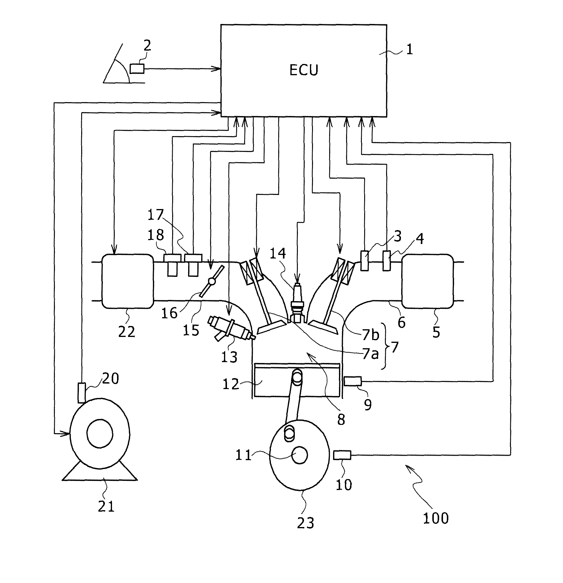
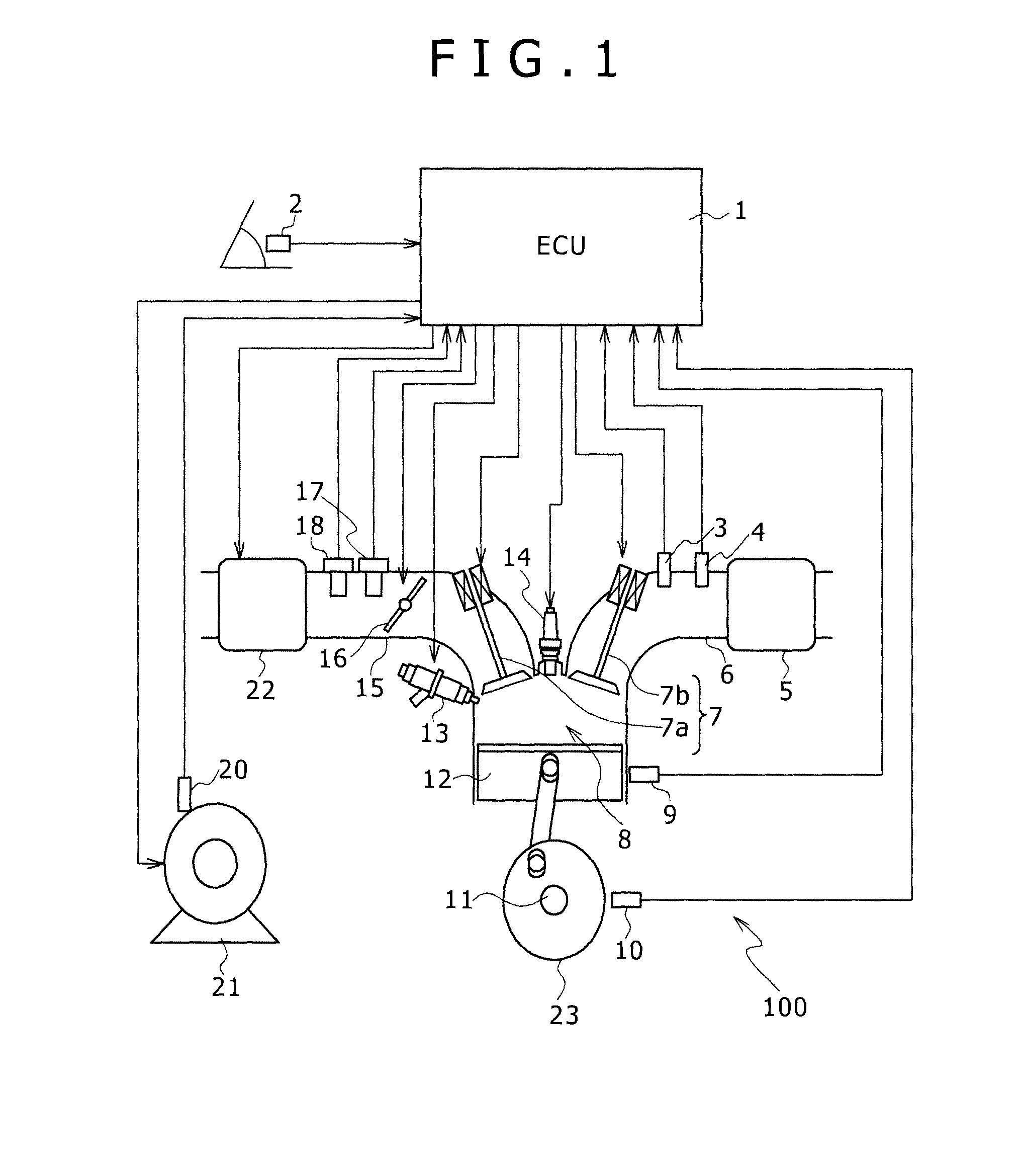
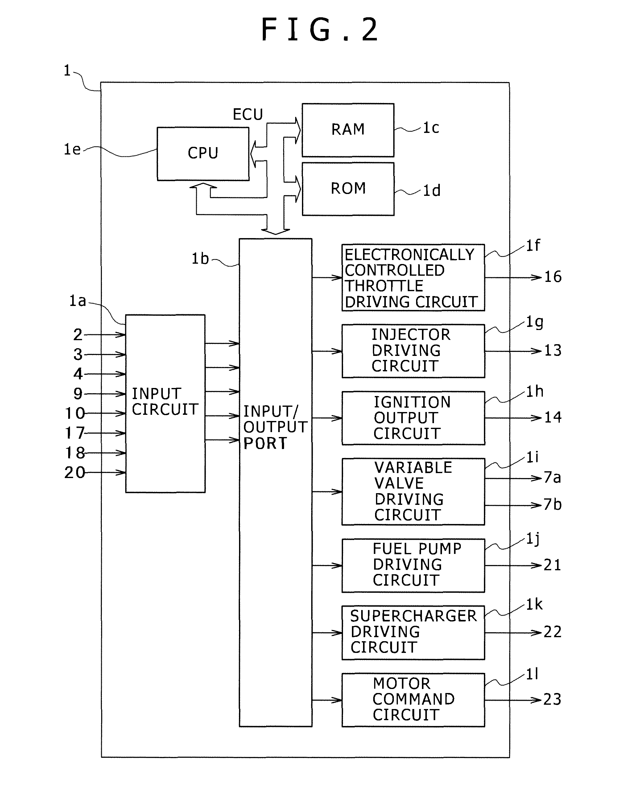
[0052]A structure of a device for controlling an internal combustion engine according to a first embodiment is described using FIG. 1. The device structure of this embodiment is assumed to be applied to a gasoline internal combustion engine for automobiles.

[0053]The internal combustion engine 100 is the gasoline internal combustion engine for automobiles that performs different combustion modes: (1) spark ignited combustion and (2) compression ignited combustion. Both combustion modes use an air-fuel mixture having the same air-fuel ratio.

[0054]Here, (1) spark ignited combustion is a method in which the air-fuel mixture fed into the internal combustion engine is ignited by an ignition plug mounted to a cylinder head and combusted and (2) compression ignited combustion is a method in which air fed into a combustion chamber is adiabatically compressed by a piston to increase its temperature and fuel is injected into this air, thus causing self-ignition and fuel combustion or a method ...

second embodiment

[0148]Next, a second embodiment of the present invention is described using FIGS. 21 through 24. As for component parts that are fundamentally the same as those of the first embodiment depicted in FIGS. 1 and 2, their descriptions are omitted.

[0149]The difference from the embodiment depicted in FIGS. 1 and 2 lies in that the second embodiment is arranged such that both a resonant knock sensor and a non-resonant knock sensor are used and a combustion noise is detected using these two knock sensors.

[0150]In FIG. 20, a non-resonant knock sensor 9 and a resonant knock sensor 24 are attached to the cylinder block and signals from these sensors are input to an input circuit 1a as present in FIG. 21.

[0151]Then, using FIG. 22, descriptions are provided about knock sensor characteristics of the non-resonant knock sensor 9 and the resonant knock sensor 24. In particular, a graph of S / N ratio as a sensitivity indicator is presented, in which the abscissa plots frequency and the ordinate plots ...

third embodiment

[0162]Next, a third embodiment of the present invention is described using FIGS. 25 through 31. As for component parts that are fundamentally the same as those of the first embodiment depicted in FIGS. 1 and 2, their descriptions are omitted.

[0163]The system structure in FIG. 25 is substantially the same as the embodiment depicted in FIGS. 1 and 2. The difference lies in that more combustion modes are applied instead of the two regions of spark ignited combustion and compression ignited combustion; i.e., the operating scope is divided into four combustion regions: (1) stoichiometric (theoretical air-fuel ratio) spark ignited combustion; (2) lean combustion; (3) exhaust gas recirculation combustion; and (4) compression ignited combustion, and combustion control is exerted on these regions. Thus, the control map within the ECU 1 is created in accordance with this. In the present embodiment:

(1) Stoichiometric spark ignited combustion is a combustion mode in which air-fuel mixture havin...


PUM


Abstract

Although a method for changing a combustion method taking place in an internal combustion engine depending on running condition is proposed, it can be considered that conditions under which a combustion noise occurs naturally differ with different methods. A detection method of prior art is not compatible with different combustion methods and the accuracy of combustion noise detection was low. Accurate combustion noise detection is enabled by identifying a combustion mode taking place in the internal combustion engine, selecting a sensed frequency or frequency band of a combustion noise sensor that detects a combustion noise in a combustion chamber of the internal combustion engine according to the combustion mode, and detecting a combustion noise.

Description

TECHNICAL FIELD[0001]The present invention relates to a method and device for detecting combustion noise to detect a combustion noise in an internal combustion engine and a device for controlling the internal combustion engine by driving a regulatory mechanism for controlling combustion in the internal combustion engine. In particular, the invention relates to a method and device for detecting combustion noise that directly or indirectly identify a condition of combustion which may take place by one of different combustion methods in a combustion chamber of the internal combustion engine and a device for controlling the internal combustion engine that controls combustion through the use of the device for detecting combustion noise so as to improve fuel efficiency performance or / and emission performance of the internal combustion engine.BACKGROUND ART[0002]It is known that a vibration sensing type knock sensor that senses vibration of the internal combustion engine is used as a means...

Claims


Application Information

Patent Timeline
Patent Type & Authority Applications(United States)
IPC IPC(8): F02D41/14
CPCG01H17/00F02D41/3017F02D2200/025G01M15/12B60W10/04F02D41/40F02P5/04F02D13/0242F02D35/027F02D41/0007F02D2041/001F02D2041/1432F02D2041/288Y02T10/12Y02T10/40F02D41/1493
Inventor OGATA, KENICHIROHWATANABE, DAISUKEOKAMOTO, TAKASHI
Owner HITACHI ASTEMO LTD
Why Eureka
Try Eureka