
LED light assembly and system

Active Publication Date: 2014-06-26
DIOLUCE
View PDF41 Cites 10 Cited by
  • Summary
  • Abstract
  • Description
  • Claims
  • Application Information

AI Technical Summary

Benefits of technology

The patent text describes a replacement light assembly and system for fluorescent light fixtures. The replacement light assembly can be used to replace existing fluorescent bulbs of various lengths. The lighting system is designed to provide more efficient, longer-life, and cooler lighting than fluorescent bulbs. It features a hanging bracket and clips for easy installation and removal of the frame from the casing. The LED based lighting system also includes a hanging bracket and clips for easy installation and removal of each end of the frame. Overall, the patent text describes a lighting solution that offers a cost-effective and energy-saving replacement for existing fluorescent light fixtures.

Problems solved by technology

Some disadvantages of fluorescent light bulbs or lamps that are used in such fixtures are that they are not very efficient and thus consume a lot of power.
For example, such fluorescent light bulbs or lamps are not very amenable to being dimmed and when they are dimmed their power factor or efficiency drops down to about 70%.
In addition, fluorescent light bulbs may not provide enough light for certain fixture locations.
Further, fluorescent light bulbs have an omni-directional light output pattern, not directional, and thus there is inherent loss of light radiated in a backwards direction (upwards instead of downwards).
Further, fluorescent light bulbs become less efficient over time and use, and are not suitable for use in certain applications such as cold weather locations.
Still further, fluorescent light bulbs tend to give off a large amount of heat, which can lead to increased air conditioning costs when used in high temperature locations and climates.

Method used


Image

  • LED light assembly and  system
  • LED light assembly and  system
  • LED light assembly and  system

Examples


Embodiment Construction

[0084]Aspects and embodiments are directed to a replacement light assembly for use in fixtures that currently use fluorescent light bulbs or lamps. Aspects and embodiments are further directed to replacement lighting systems for use in applications that currently use fluorescent light fixtures. In particular, aspects and embodiments of the light assembly disclosed herein can be used to replace existing 2-foot, 4-foot, 8-foot or any length tubular fluorescent light bulbs. Further, aspects and embodiments of the lighting system systems disclosed herein can be configured to retro-fit existing overhead light fixtures or can be provided as new light fixtures. Further, aspects and embodiments of the light assembly and lighting systems disclosed herein can be configured to replace any type of fluorescent light bulb or lamp. Further, aspects and embodiments of the light assembly and lighting system disclosed herein provide for using less light assemblies than fluorescent bulbs currently use...


PUM


Abstract

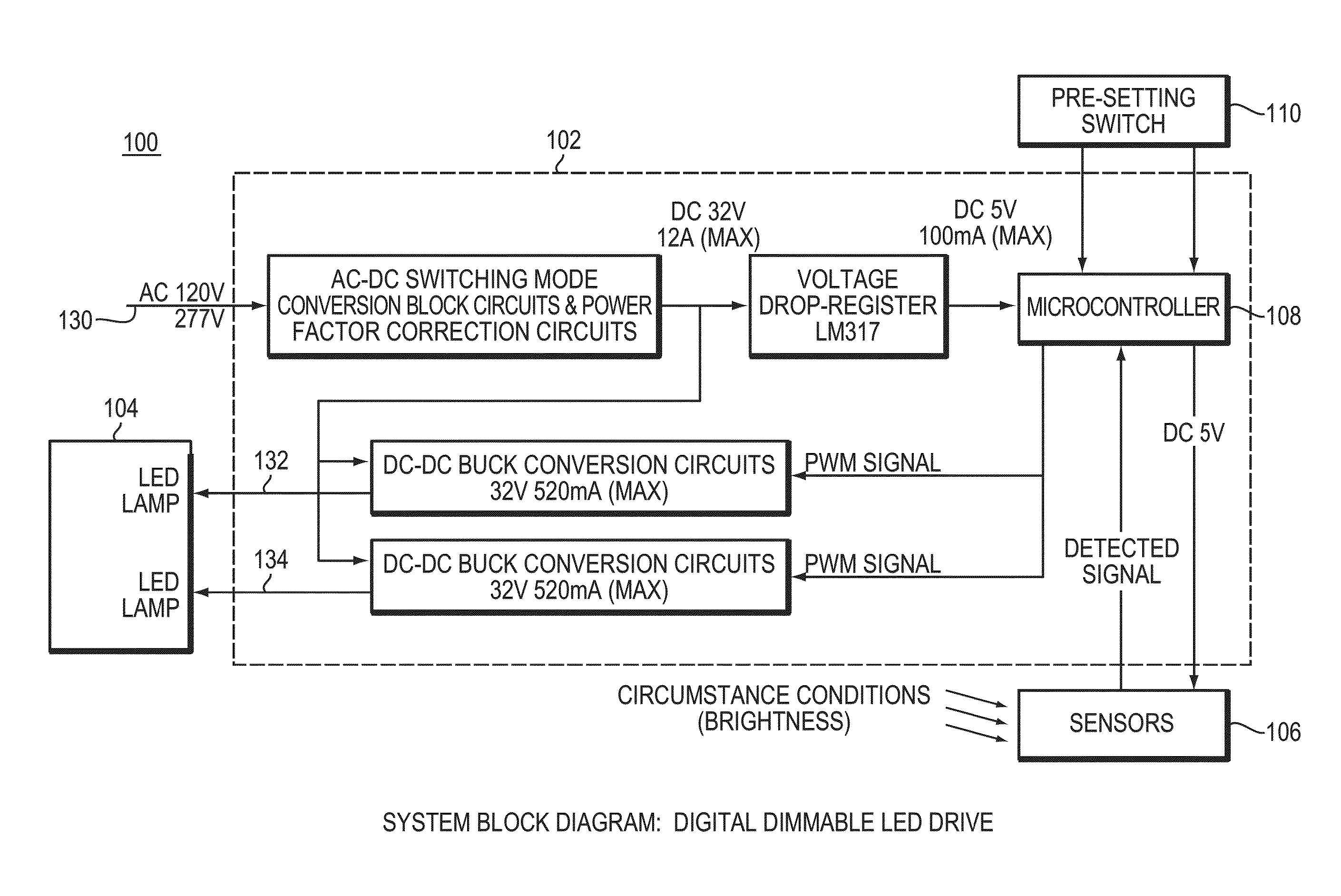
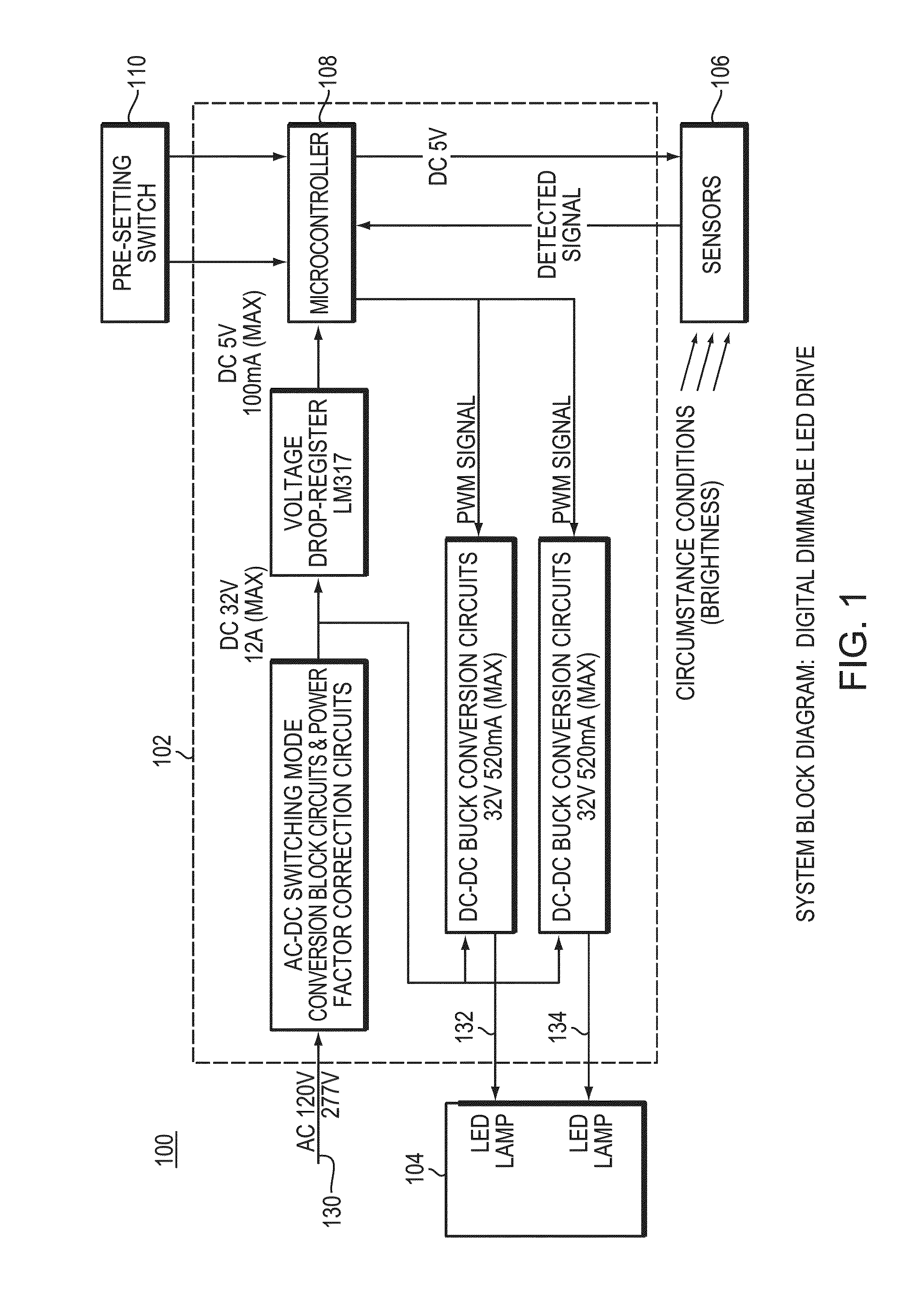
An LED based light assembly and lighting system is disclosed. The lighting system includes at least one light assembly comprising a plurality of LED chips, a controller and a power supply module. The controller is configured to receive an input signal and to provide an output control signal for controlling power to the at least one light assembly. The power supply module is configured to receive a standard voltage and current signal and to provide a power signal to the at least one light assembly to power the at least one light assembly in response to the control signal.

Description

BACKGROUND[0001]Overhead light fixtures used in parking garages, office space, industrial warehouses, and the like often include fluorescent light bulbs or lamps, and typically include 3 fluorescent light bulbs. Some disadvantages of fluorescent light bulbs or lamps that are used in such fixtures are that they are not very efficient and thus consume a lot of power. For example, such fluorescent light bulbs or lamps are not very amenable to being dimmed and when they are dimmed their power factor or efficiency drops down to about 70%. In addition, fluorescent light bulbs may not provide enough light for certain fixture locations. Further, fluorescent light bulbs have an omni-directional light output pattern, not directional, and thus there is inherent loss of light radiated in a backwards direction (upwards instead of downwards). Further, fluorescent light bulbs become less efficient over time and use, and are not suitable for use in certain applications such as cold weather location...

Claims


Application Information

Patent Timeline
IPC IPC(8): H05B33/08H05B44/00
CPCH05B33/0854F21V23/003F21K9/278H05B47/11Y02B20/00Y02B20/30Y02B20/40H05B45/3578H05B45/375H05B47/13H05B31/50H05B45/52H05B47/115H05B45/12F21V29/70F21K9/272F21K9/275F21Y2103/10F21Y2115/10F21S8/043F21V7/00F21V17/16F21V23/02F21V23/04
Inventor PLOURDE, ROGERYI, HAE N.SHIN, BYOUNG K.
Owner DIOLUCE
Learn More