
Systems and methods for selecting parameters using contrast and noise

a technology of contrast noise and selection parameters, applied in the field of imaging systems and methods, can solve the problems of affecting the patient's image, and lack of guidance, and achieving the effect of little or no adjustment for patient or usage in certain systems

Active Publication Date: 2014-06-26
GENERAL ELECTRIC CO
View PDF11 Cites 14 Cited by
  • Summary
  • Abstract
  • Description
  • Claims
  • Application Information

AI Technical Summary

Benefits of technology

The patent text describes an imaging system with a identification module, analysis module, and determination module that can identify the type of scan to be performed and determine the necessary settings for the scan based on the object being scanned. This system can select the optimal settings for the scan based on the image contrast and tolerable noise for each setting combination. The technical effect of this patent is to provide a more efficient and accurate way to scan objects using an imaging system.

Problems solved by technology

Lower x-ray tube current levels may lead to streaking or other artifacts in an image.
However, conventional voltage selection may be mostly responsive to the preference of the physician, and thus typically may lack sufficient guidance.
In terms of tube voltage, however, little or no adjustment may have been made for patient or usage in certain systems.
Because of the interaction of tube voltage and current, image quality may suffer and / or unacceptable levels of noise may be present in scans for which tube voltage has been adjusted.
Further, selection of tube voltage may be difficult, complicated, or poorly explained, so that the lack of ease of use has resulted in practitioner's often failing to adjust a tube voltage for a particular patient or procedure.
Because of the complexity, for example, of interactions between aspects of systems and / or between parameters defining the operation of scanning systems, it is difficult to adjust tube voltage, for example to optimize radiation dose while maintaining tolerable image quality.
Therefore, non-optimal usage of a scanning system may result.

Method used


Image

  • Systems and methods for selecting parameters using contrast and noise
  • Systems and methods for selecting parameters using contrast and noise
  • Systems and methods for selecting parameters using contrast and noise

Examples


Embodiment Construction

[0013]The foregoing summary, as well as the following detailed description of various embodiments, will be better understood when read in conjunction with the appended drawings. To the extent that the figures illustrate diagrams of the functional blocks of the various embodiments, the functional blocks are not necessarily indicative of the division between hardware and / or circuitry. Thus, for example, one or more of the functional blocks (e.g., processors or memories) may be implemented in a single piece of hardware (e.g., a general purpose signal processor or a block of random access memory, hard disk, or the like) or multiple pieces of hardware. Similarly, the programs may be stand-alone programs, may be incorporated as subroutines in an operating system, may be functions in an installed software package, and the like. It should be understood that the various embodiments are not limited to the arrangements and instrumentality shown in the drawings.

[0014]Described herein are variou...


PUM


Abstract

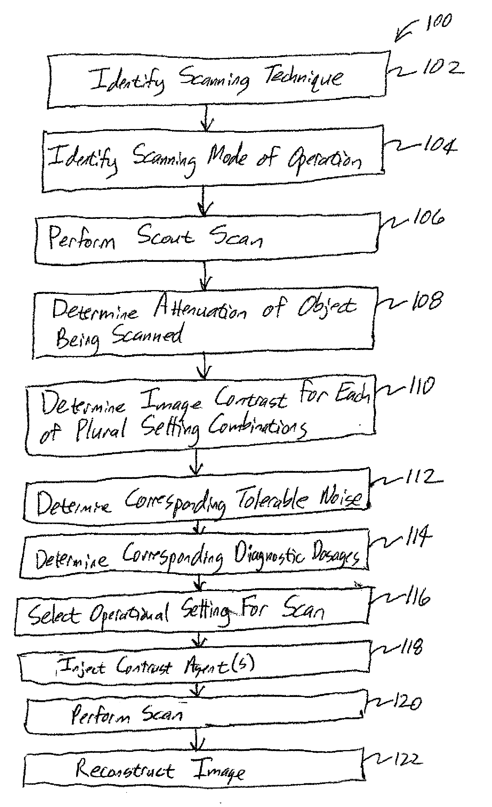
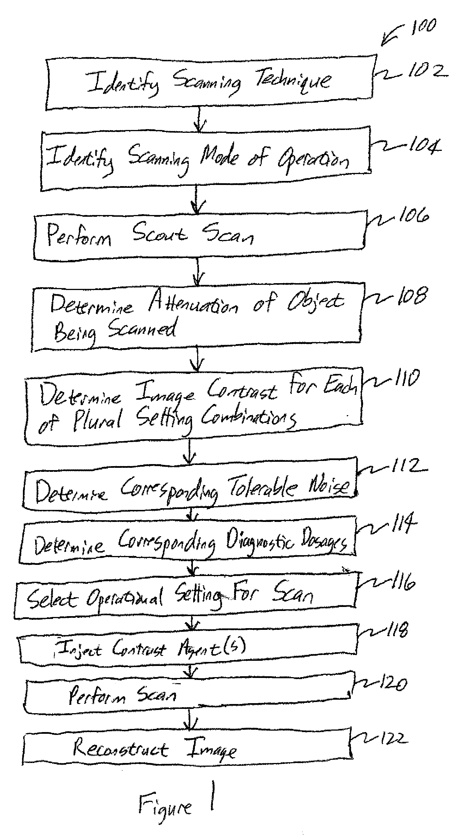
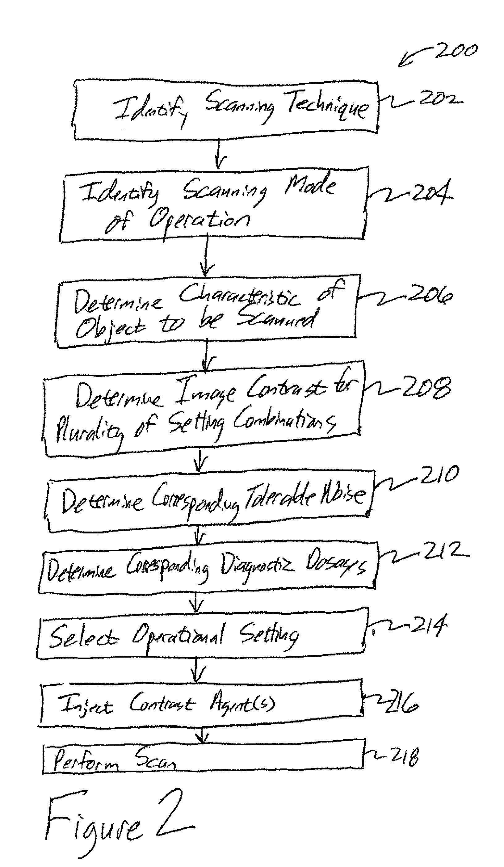
An imaging system includes an identification module, an analysis module, and a determination module. The identification module is configured to identify a scanning mode of operation. The analysis module is configured to determine an attenuation for an object for a scan to be performed on the object. The determination module is configured to determine an image contrast for each of plural setting combinations, determine a corresponding tolerable noise for the image contrast for each of the setting combinations based on the scanning mode of operation, and determine a corresponding diagnostic dosage for each setting combination, the diagnostic dosages corresponding to the image contrast and tolerable noise for the corresponding setting combination. The determination module is also configured to select an operational setting for the scan to be performed using the dosages determined.

Description

BACKGROUND OF THE INVENTION[0001]The subject matter disclosed herein relates generally to imaging systems and methods, and more particularly, to systems and methods for selecting parameters for imaging.[0002]Computed Tomography (CT) imaging systems typically include an x-ray source and a detector. As the x-rays pass from the source through the object being imaged, the x-rays become attenuated before impinging upon the detector. The intensity of the attenuated beam radiation received at the detector is responsive to the attenuation of the x-rays by the object, with detector elements producing separate electrical signals responsive to the beam attenuation at the detector element location. These electrical signals may be referred to as x-ray attenuation measurements. Further, the x-ray source and the detector array may be rotated around the object to be imaged such that an angle at which an x-ray beam intersects the object changes. A group of x-ray attenuation measurements, or projecti...

Claims


Application Information

Patent Timeline
Patent Type & Authority Applications(United States)
IPC IPC(8): A61B6/03
CPCA61B6/032A61B6/5258A61B6/54A61B6/542
Inventor STEVENS, GRANT MOREYNILSEN, ROY A.
Owner GENERAL ELECTRIC CO
Learn More