Vehicle control device

Inactive Publication Date: 2014-06-26
DENSO CORP
View PDF4 Cites 33 Cited by
  • Summary
  • Abstract
  • Description
  • Claims
  • Application Information

AI Technical Summary

Benefits of technology

[0007]It is therefore desired to provide a vehicle control device capable of determining a driving route optimally adapted to a shape of a driving lane of an own vehicle to which the vehicle control device is mounted.
[0008]An exemplary embodiment provides a vehicle control device comprised of a driving lane detection section, a basic steering amount calculation section, a posture detection section, an offset distance detection section, a correction steering amount calculation section and an instruction steering amount calculation section. The driving lane detection section detects a driving lane on which own vehicle is driving. The basic steering amount calculation section calculates a basic steering amount which is a steering control amount to drive the own vehicle on a basic route. The basic route is extended along a shape of the driving, lane of the own vehicle. The posture detection section detects a posture of the own vehicle designated by a lateral position and an angle of yaw of the own vehicle. The lateral position of the own vehicle is a position in a width direction of the driving lane. A route direction is a tangential direction of the basic route at the position of the own vehicle. The angle of yaw is a slope of the front direction of the own vehicle from the route direction.
[0009]The offset distance detection section detects, as an offset distance, a distance between the basic route and the lateral position of the own vehicle. The correction steering amount calculation section determines a virtual target point which is apart f

Problems solved by technology

However, the conventional vehicle control device disclosed in the patent document previously described has a problem of it being difficult to determine a driving route optimally ada

Method used


Image

  • Vehicle control device
  • Vehicle control device
  • Vehicle control device

Examples


first exemplary embodiment

[0047]A description will be given of a vehicle control device according to a first exemplary embodiment with reference to FIG. 1 to FIG. 8A, FIG. 8B and FIG. 8C.

[Overall Structure]

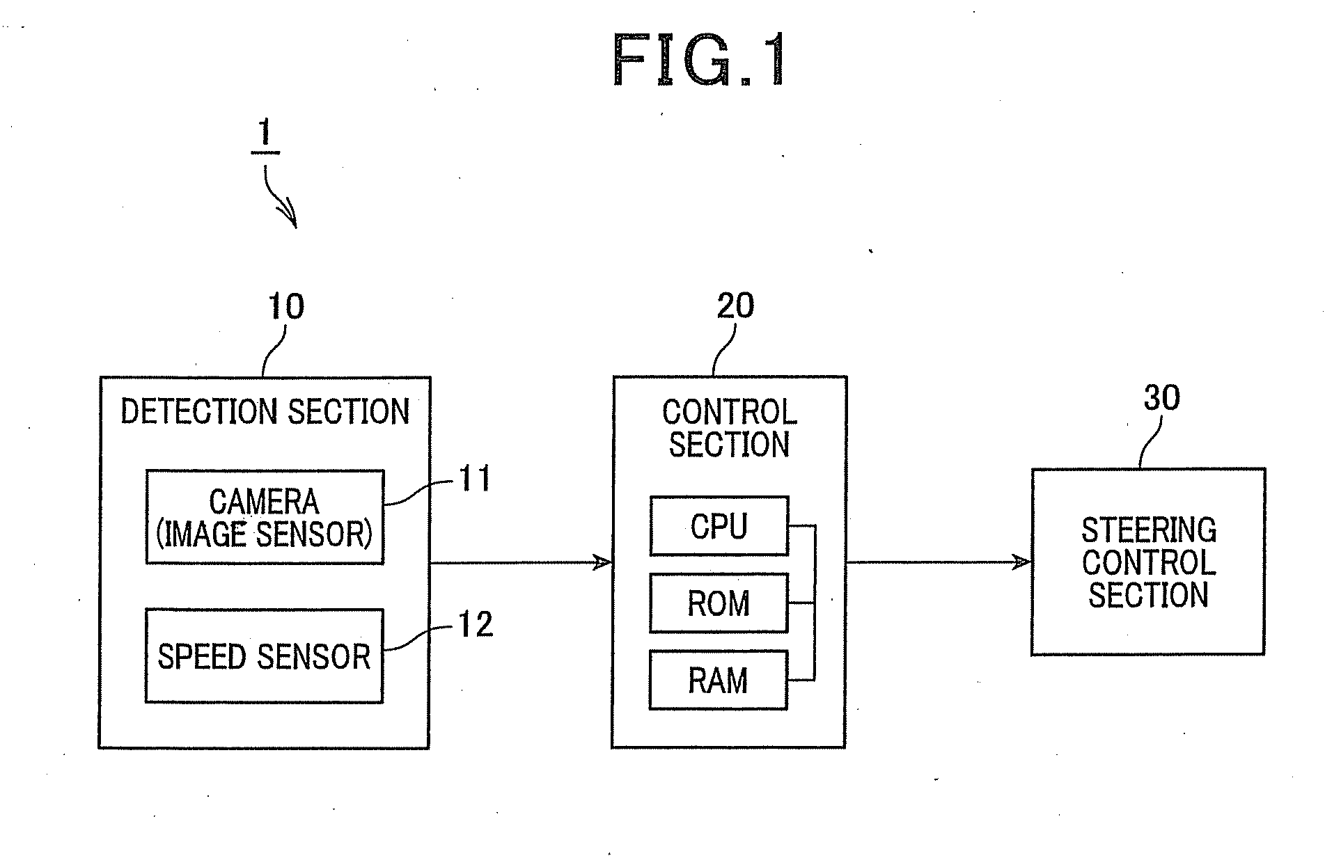
[0048]FIG. 1 is a view showing a block diagram of the vehicle control device according to the first exemplary embodiment. As shown in FIG. 1, the vehicle control device 1 is comprised of a detection section 10, a control section 20 and a steering control section 30. The detection section 10 detects a surrounding environment of own vehicle and vehicle conditions of the own vehicle. The control section 20 determines a driving route, on which the own vehicle is running, on the basis of the detection results of the detection section 10. The control section 20 generates a steering instruction. The own vehicle can drive on the determined detection route on the basis of the generated steering instruction. The steering control section 30 receives the steering instruction transmitted from the control section 20, an...

second exemplary embodiment

[0081]A description will be given of the vehicle control device according to a second exemplary embodiment with reference to FIG. 9, FIG. 10A and FIG. 10B.

[Structure]

[0082]The vehicle control device according to the second exemplary embodiment has the same structure of the vehicle control device 1 according to the first exemplary embodiment. In particular, the vehicle control device according to the second exemplary embodiment is different in a part of the correction steering amount calculation process performed by the control section 20 from the vehicle control device 1 according to the first exemplary embodiment. The difference between the second exemplary embodiment and the first exemplary embodiment will be explained, and the explanation of the same components is omitted here.

[Correction Steering Amount Calculation Process]

[0083]FIG. 9 is a view showing a flow chart for calculating a correction steering amount by the vehicle control device according to a second exemplary embodim...

third exemplary embodiment

[0091]A description will be given of the vehicle control device according to a third exemplary embodiment with reference to FIG. 11 and FIG. 12A and FIG. 12B.

[0092]The vehicle control device according to the third exemplary embodiment has the same structure of the vehicle control device according to the first exemplary embodiment. In particular, the vehicle control device according to the third exemplary embodiment is different in the correction steering amount calculation process performed by the control section 20 from the vehicle control device according to the first exemplary embodiment. The explanation of the same components and operations between the third exemplary embodiment and the first exemplary embodiment is omitted here.

[Correction Steering Amount Calculation Process]

[0093]FIG. 11 is a view showing a flow chart for calculating a correction steering amount by the vehicle control device according to the third exemplary embodiment.

[0094]When compared with the correction st...


PUM


Abstract

In a vehicle control device, a basic steering amount calculation section calculates a basic steering amount to drive an own vehicle on a basic route along a driving lave. A posture detection section detects a vehicle posture state indicated by a lateral position and an angle of yaw. An offset distance detection section detects an offset distance between the basis route and the lateral position. A correction steering amount calculation section calculates a correction steering amount as a steering control amount to drive the own vehicle along a virtual correction route. The posture of the own vehicle is alien with a predetermined target posture at a predetermined virtual target point by using the virtual correction route. An instruction steering amount calculation section calculates an instruction steering amount on the basis of the basic steering amount and the correction steering amount.

Description

CROSS-REFERENCE TO RELATED APPLICATION[0001]This application is related to and claims priority from Japanese Patent Applications No. 2012-279592 filed on Dec. 21, 2012, and No. 2013-123846 filed on Jun. 12, 2013, the contents of which are hereby incorporated by reference.BACKGROUND OF THE INVENTION[0002]1. Field of the Invention[0003]The present invention relates to vehicle control devices for performing an automatic steering control.[0004]2. Description of the Related Art[0005]Recently, a vehicle control device using a lane keep assist (LKA) technique has been developed, which controls a vehicle to run on a driving lane without deviation from the driving lane. There is known a device as this kind of the vehicle control device. For example, a patent document, Japanese patent laid open publication No. JP2007-261449, discloses a device for determining a target point on a driving lane which is in front of a vehicle, for setting a target route so that the vehicle passes through the targ...

Claims


Application Information

Patent Timeline
IPC IPC(8): B62D6/00
CPCB62D6/00B62D1/28B62D15/025
Inventor UEDA, YUSUKETSURUTA, TOMOHIKOHATOH, TAKESHIKONDOH, TAKAYUKIINOUE, NAOYA
Owner DENSO CORP
Why Eureka
Try Eureka