Composite open/spaced matrix composite support structures and methods of making and using thereof

a composite support and open/spaced matrix technology, applied in the direction of photovoltaic supports, machine/engines, rod connections, etc., can solve the problems of medium-duty construction equipment, and achieve the effect of strong structure, rapid deployment and cost-effectiveness

Inactive Publication Date: 2014-07-03
HOLT DREW RYAN
View PDF0 Cites 23 Cited by
  • Summary
  • Abstract
  • Description
  • Claims
  • Application Information

AI Technical Summary

Benefits of technology

[0006]The present invention is of open lattice composite matrix support structures comprising a plurality of filaments or fibers layered in a interweaved configuration that intersect at a plurality of nodes and are set into a stabilized position by embedding them within one or more cured polymeric materials. Various embodiments of the open / spaced matrix composite support structures of the present invention are of a telescoping and / or collapsible design that allow such support structures to be compact for cost effective transport and rapidly deployed due to their ultra light yet very strong structure. The composite support structures of the present invention are generally light weight, durable and provide a stable and effective structure that can replace pole or mast systems made from much heavier materials such as wood, steel, aluminum, reinforced concrete and the like.
[0007]The advantages of the present invention include, without limitation, that it is portable and exceedingly easy to transport with a low cost to install due to the open matrix composite strut material that has an exceedingly high strength to weight ratio. Furthermore, it is easy to move these devices in the field because or there dramatically reduced weight versus towers and poles made from heavier materials, such as metals or woods. Moving such devices typically requires man power and small tools with a potential for medium duty construction equipment. Further, the devices generally can be field deployed without the need to build approved roads, the need and use poured concrete and / or the use of heavy cranes for installation.
[0008]In broad embodiment, the present invention is a lattice structure (e.g. static or telescoping tower) of any open lattice composite, thereby providing reduced mass, installation ease and cost reduction.

Problems solved by technology

Moving such devices typically requires man power and small tools with a potential for medium duty construction equipment.

Method used


Image

  • Composite open/spaced matrix composite support structures and methods of making and using thereof
  • Composite open/spaced matrix composite support structures and methods of making and using thereof
  • Composite open/spaced matrix composite support structures and methods of making and using thereof

Examples


Embodiment Construction

[0084]The embodiments of the present invention described below are not intended to be exhaustive or to limit the invention to the precise forms disclosed in the following detailed description. Rather, the embodiments are chosen and described so that others skilled in the art can appreciate and understand the principles and practices of the present invention.

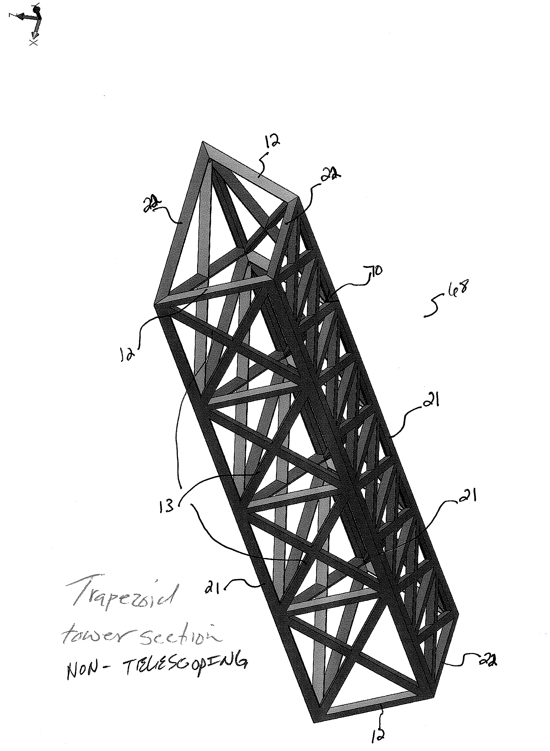
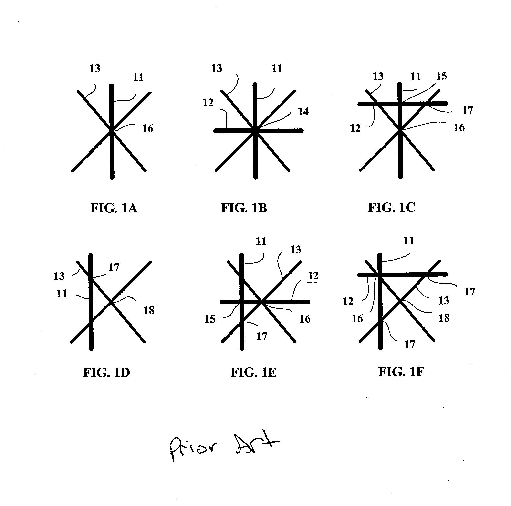
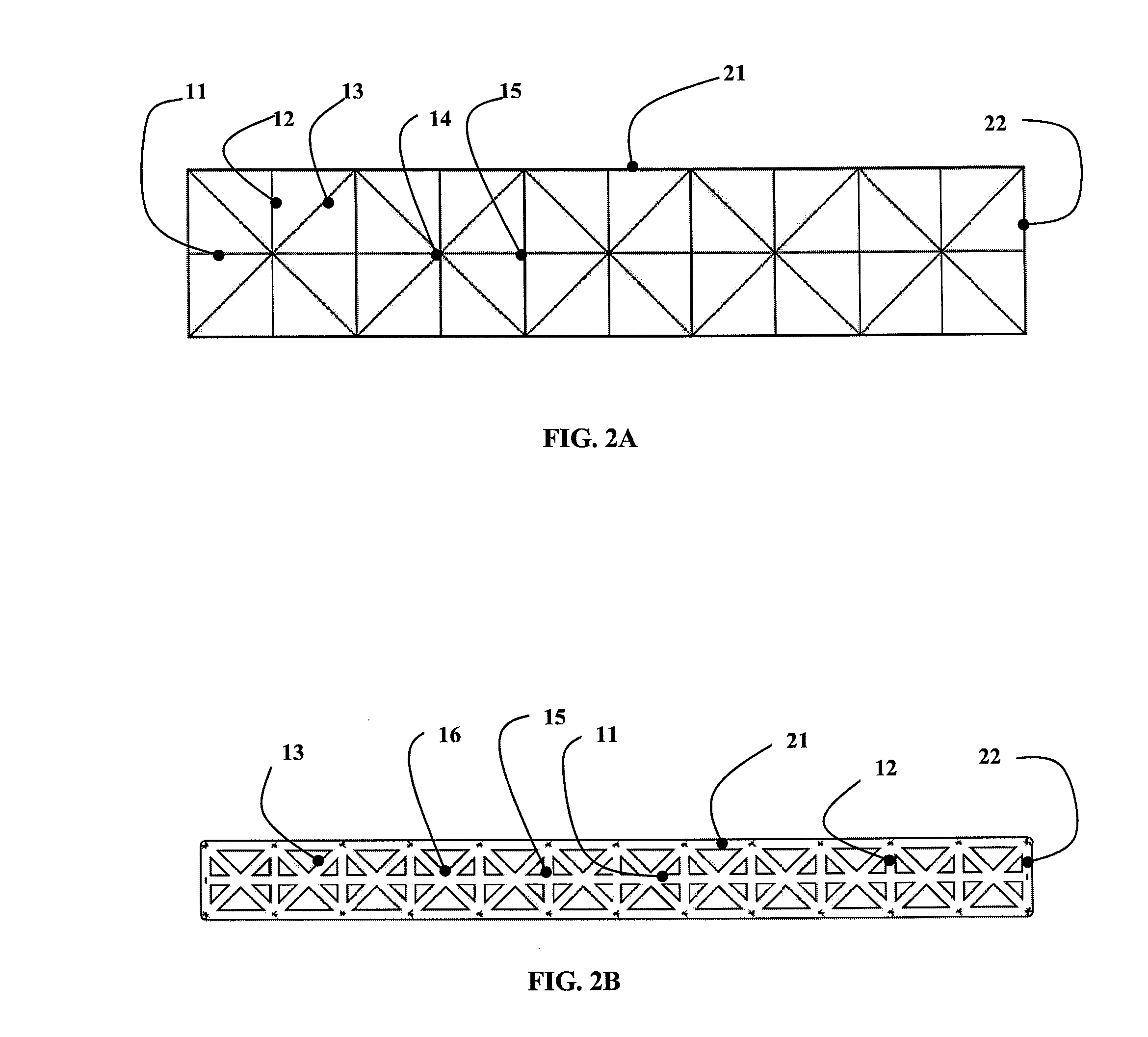
[0085]Referring now to the invention in more detail, the open lattice composite matrix support structures of the present invention include a plurality of fiber / polymer members (e.g. fiber / polymer strands, tapes, strings . . . ), including a plurality of filaments or fibers layered in an interweaved configuration that intersect at a plurality of nodes. The filaments or fibers of the composite members are set into a stabilized position by embedding them within one or more cured polymeric materials. Furthermore, in various embodiments of the present invention, the fiber / polymer composite is cured while placed within channels on an e...


PUM

PropertyMeasurementUnit
structureaaaaaaaaaa
lattice structureaaaaaaaaaa
lattice structuresaaaaaaaaaa

Abstract

A lattice support structure or tower comprising one or more open matrix composite strut members connecting a series of interlocking connectors to create a ridged support platform for telecommunications, surveillance, renewable energy, lighting and energy transmission applications. Embodiments of the invention are telescoping for ease of transport and erection. The erection and deployment can be achieved through means of automatic deployment or manual.

Description

CROSS-REFERENCE TO RELATED APPLICATION[0001]This application claims priority to U.S. Provisional Application No. 61 / 488,041 filed on May 19, 2011, the contents of which are incorporated by reference herein.FIELD OF THE INVENTION[0002]The present invention is related to lattice support structures used in the technical field of rapid deployable tower and mast systems. In various embodiments, the lattice structures of the present invention are produced and used in the technical fields including, but not limited to, renewable energy power production, energy / power transmission, communications, surveillance, lighting, containment fencing, and antenna support.BACKGROUND OF THE INVENTION[0003]Conventional telecommunications and renewable energy production support structures are constructed of wood, steel (e.g. galvanized, stainless and painted steel . . . ) aluminum, and reinforced concrete. Such structures are exceedingly difficult to transport and very difficult to disassemble and move on...

Claims


Application Information

Patent Timeline
Patent Type & Authority Applications(United States)
IPC IPC(8): E04C3/36B29C70/56
CPCB29C70/56E04C3/36E04H12/02E04H12/16E04H12/182E04H12/2223E04H12/34E04H12/345E04H12/347F03D11/04F16B7/20H01Q1/12H01L31/0422H01L31/0424H01Q1/1242F05B2240/9121F05B2240/913F05B2240/9151F05B2280/6003Y02E10/50Y02E10/728F16B7/042F16B7/182B29C53/824B29C70/24H02S20/00H02S30/00B29C33/485F03D13/20Y02E10/72Y02P70/10
Inventor HOLT, DREW RYAN
Owner HOLT DREW RYAN
Why Eureka
Try Eureka