Constant-voltage circuit

Inactive Publication Date: 2014-07-03
PANASONIC INTELLECTUAL PROPERTY MANAGEMENT CO LTD
View PDF3 Cites 16 Cited by
  • Summary
  • Abstract
  • Description
  • Claims
  • Application Information

AI Technical Summary

Benefits of technology

[0034]In the above constant-voltage circuit, the protection circuit may include: a first current/voltage converter configured to convert the current generated by the first sense transistor into a first voltage; a first switch whose conduction is controlled in accordance with the first voltage such that a current corresponding to the first voltage flows through the first switch; a second current/voltage converter configured to convert the current flowing through the first switch into a second voltage; and a second switch interposed between the input terminal and the control terminal of the output transistor, the second switch be

Problems solved by technology

As a result, even if the current has such a value at which a normal operation is

Method used


Image

  • Constant-voltage circuit
  • Constant-voltage circuit
  • Constant-voltage circuit

Examples


embodiment 1

[0048][Example of Configuration of Constant-Voltage Circuit]

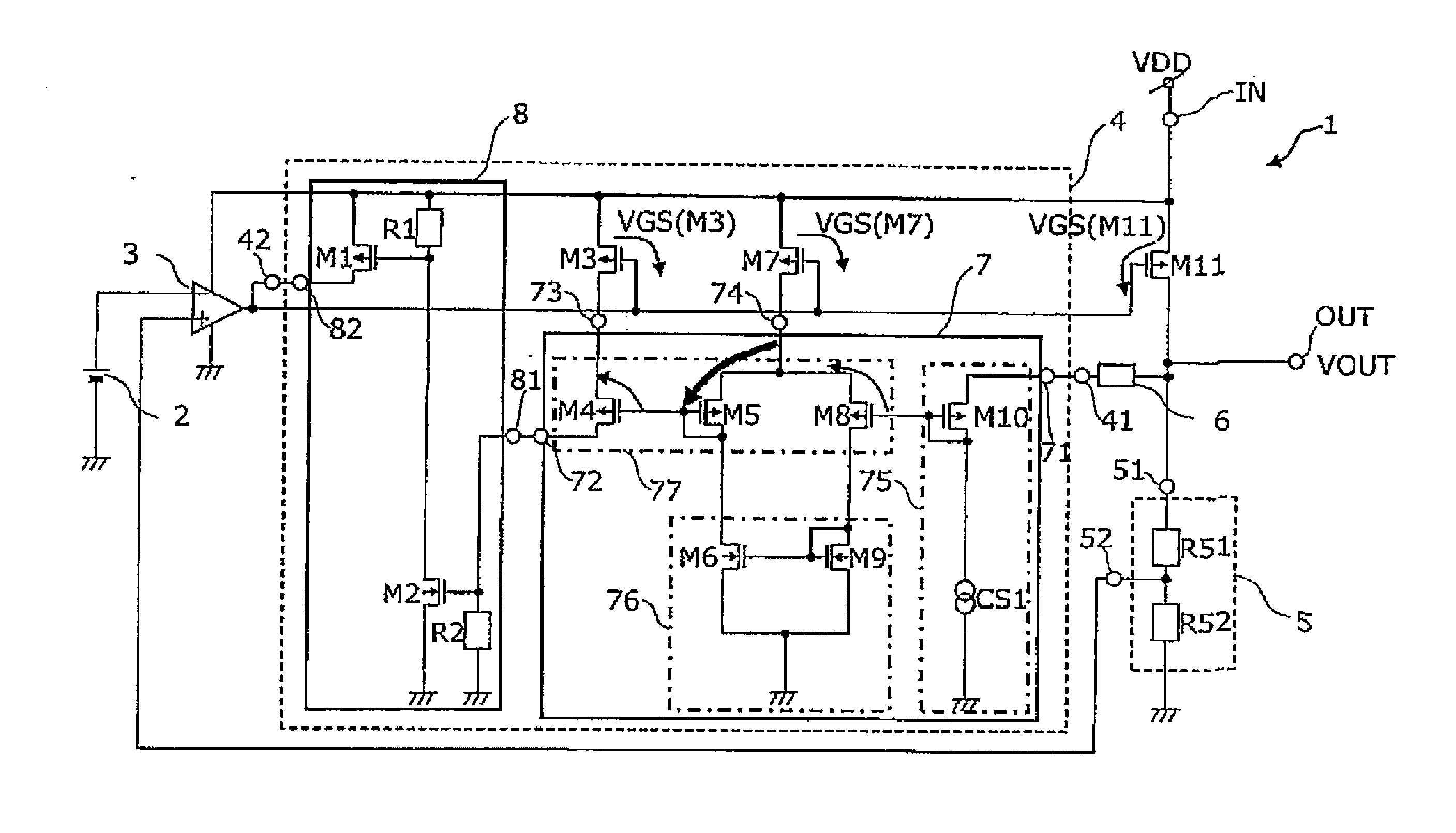
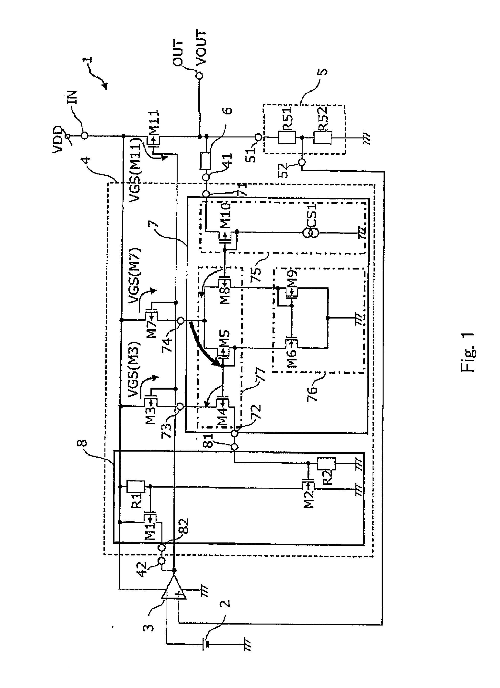
[0049]FIG. 1 shows an example of the configuration of a constant-voltage circuit according to Embodiment 1 of the present invention.

[0050]A constant-voltage circuit 1 shown in FIG. 1 includes: an input terminal IN; an output terminal OUT; a constant voltage source 2; an error amplifier 3; an overcurrent protection circuit 4; a voltage divider circuit 5; an output transistor M11; and a protective resistor 6. The protective resistor 6 herein may be configured as a resistance element or realized by interconnect resistance. The output transistor M11 is configured as a PMOS transistor. The input terminal IN is connected to a source terminal of the output transistor M11. A gate terminal of the output transistor M11 is connected to an output terminal of the error amplifier 3. The constant voltage source 2 is connected to an inverting input terminal of the error amplifier 3. An output terminal 52 of the voltage divider circuit 5 is...

embodiment 2

[0126]FIG. 6 shows the configuration of a constant-voltage circuit according to Embodiment 2 of the present invention. Embodiment 2 is different from Embodiment 1 of FIG. 1 in that, in Embodiment 2, the constant current source CS 1 of the voltage level adjusting circuit 7 is replaced by a resistor R7. The operation of the voltage level adjusting circuit 7 is performed in the same manner as that in Embodiment 1 of FIG. 1. It should be noted that since the terminal voltage at the output terminal OUT is always kept as a desired output voltage VOUT owing to the operation of the error amplifier 3, the voltage of the input terminal 71 is also always kept constant, and a current flowing through the resistor R7 is constant. As a result, the operation is performed in the same manner as that in the case where the constant current source CS1 is used.

[0127]Therefore, Embodiment 2 provides the same advantageous effects as those provided in the case where the constant current source CS 1 is used ...


PUM


Abstract

A constant-voltage circuit having an overcurrent protection circuit which includes: a first sense transistor, one main terminal connected to an input terminal of the constant-voltage circuit and a control terminal connected to a control terminal of an output transistor generates a current corresponding to an output current from the output transistor; a voltage level adjusting circuit configured to generate a voltage corresponding to a voltage of a main terminal of the output transistor at an output terminal side of the constant-voltage circuit by extracting a current that is not affected by a change in the output current from the output transistor, and adjust a voltage of another main terminal of the first sense transistor such that the adjusted voltage becomes equal to the generated voltage; and a protection circuit to control a control voltage applied from an error amplifier to the control terminal of the output transistor.

Description

[0001]This is a continuation application under 35 U.S.C. 111(a) of pending prior International Application No. PCT / JP2012 / 001639, filed on Mar. 9, 2012.[0002]The disclosure of Japanese Patent Application No. 2011-210913, filed on Sep. 27, 2011, including the specification, drawings and claims is incorporated herein by reference in its entirety.BACKGROUND OF THE INVENTION[0003]1. Field of the Invention[0004]The present invention relates to constant-voltage circuits.[0005]2. Description of the Related Art[0006]A constant-voltage circuit configured to supply a constant voltage to a load includes an overcurrent protection circuit, which limits a load current value when the load current has exceeded a rated current in order to protect the inside of the circuit and the load. FIG. 7 is a circuit diagram of a conventional constant-voltage circuit including an overcurrent protection circuit disclosed in Japanese Patent No. 4574902.[0007]First, a constant-voltage circuit 100 shown in FIG. 7 i...

Claims


Application Information

Patent Timeline
IPC IPC(8): G05F1/573
CPCG05F1/573G05F1/575
Inventor YAJIMA, HIROSHIKIHARA, HIDEYUKIUEHARA, TAKAHIRO
Owner PANASONIC INTELLECTUAL PROPERTY MANAGEMENT CO LTD
Why Eureka
Try Eureka