Cuff for arterial blood pressure monitor

a blood pressure monitor and cuff technology, applied in the field of non-invasive monitoring of arterial blood pressure, can solve the problems of insufficient measurement accuracy, additional errors, and the above-referenced cuff design, and achieve the effect of improving the signal-to-noise ratio of the signals provided by the pressure sensor, convenient insertion, and more accurate blood pressure measuremen

Inactive Publication Date: 2014-07-03
HELEN OF TROY LIMITED
View PDF0 Cites 21 Cited by
  • Summary
  • Abstract
  • Description
  • Claims
  • Application Information

AI Technical Summary

Benefits of technology

[0012]The second section and the support are mutually arranged within the gravitational field to direct a vector of the gravitational field away from the arterial side and toward a rear side of the patient's limb, such that substantially no gravitational force is applied to the pressurizing device. In this arrangement, the force generated by the limb within the gravitational field is instead absorbed by the second section and the support. The cuff has a variable geometry that allows the patient's limb to be easily inserted and then fixedly gripped so that it may be supported by the second section. By diverting the effects of gravitational force away from the pressurizing device, a signal-to-noise ratio of the signals provide by the pressure sensor is improved for more accurate blood pressure measurement

Problems solved by technology

The auscultatory method can only be used to determine systolic and diastolic pressures, and it does not determine mean pressure.
In addition, when the cuff is positioned on or near the wrist, the wrist should be elevated approximately at the aorta level, otherwise a hydrostatic pressure of blood will cause additional errors.
Generally speaking, with consideration of the above-described objectives, prior art pressurizing cuffs have had the following deficiencies: a need for a manual adjustment of the cuff size to match the limb size, and deleterious effects caused by hydrostatic pressure and the limb weight on the accuracy of the pressure measurement.
However, each of the above-referenced cuff designs fails to provide sufficient measurement accuracy.

Method used


Image

  • Cuff for arterial blood pressure monitor
  • Cuff for arterial blood pressure monitor
  • Cuff for arterial blood pressure monitor

Examples


Embodiment Construction

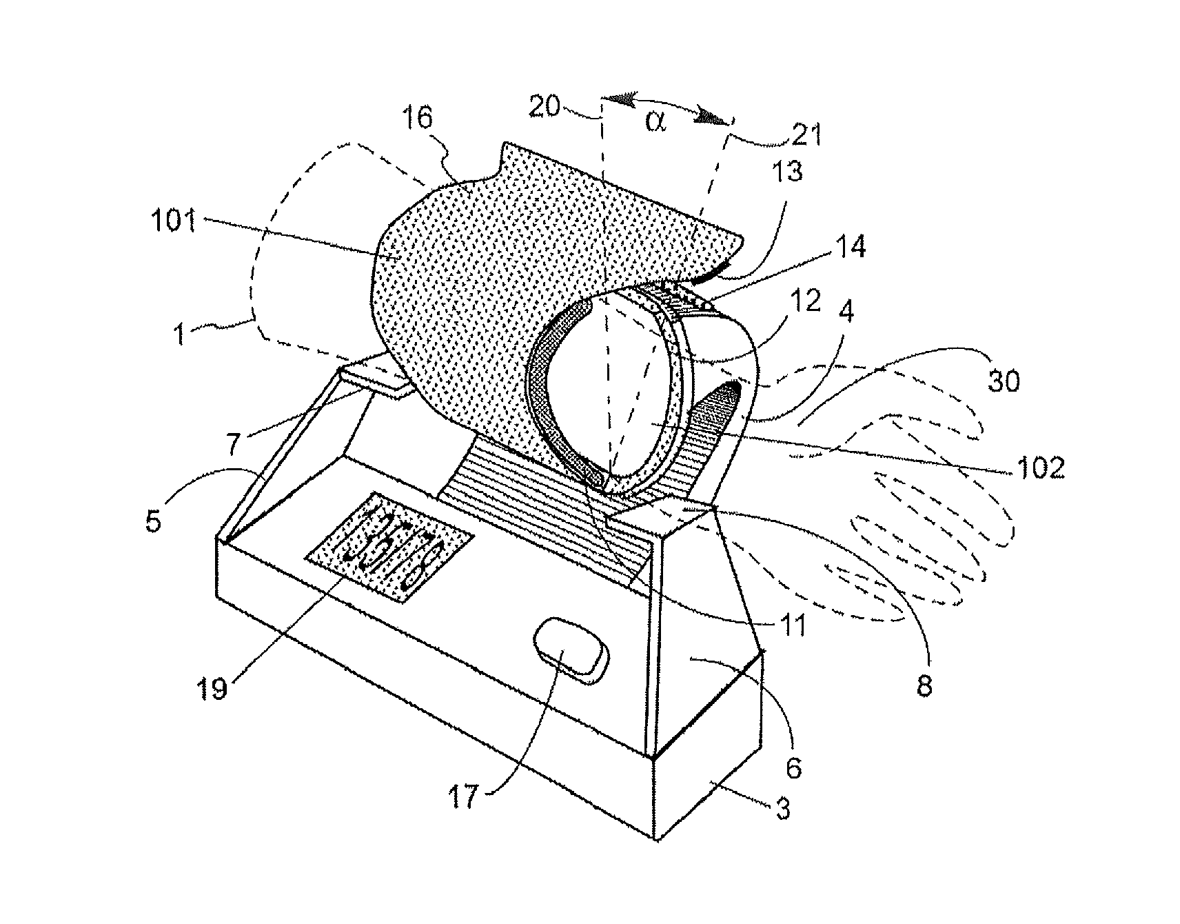
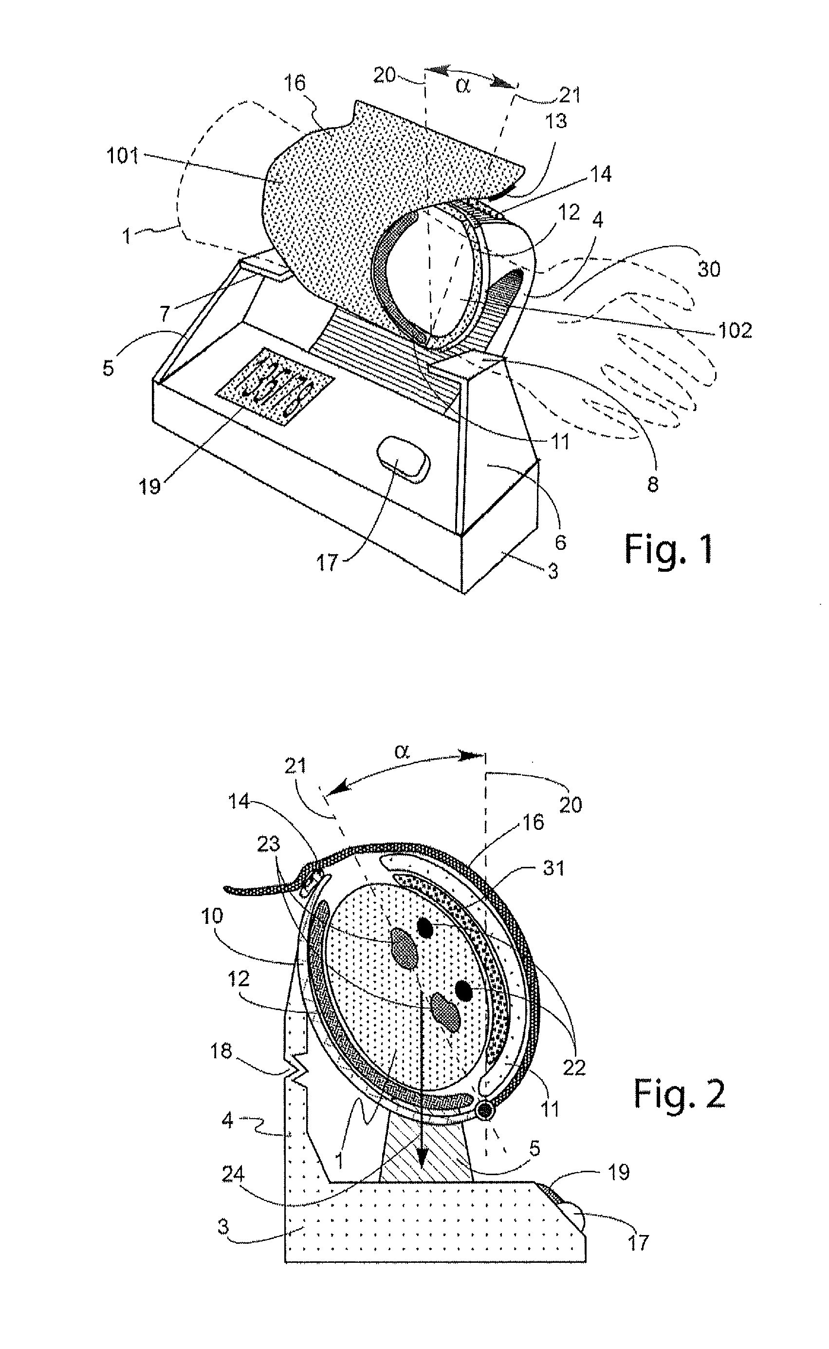
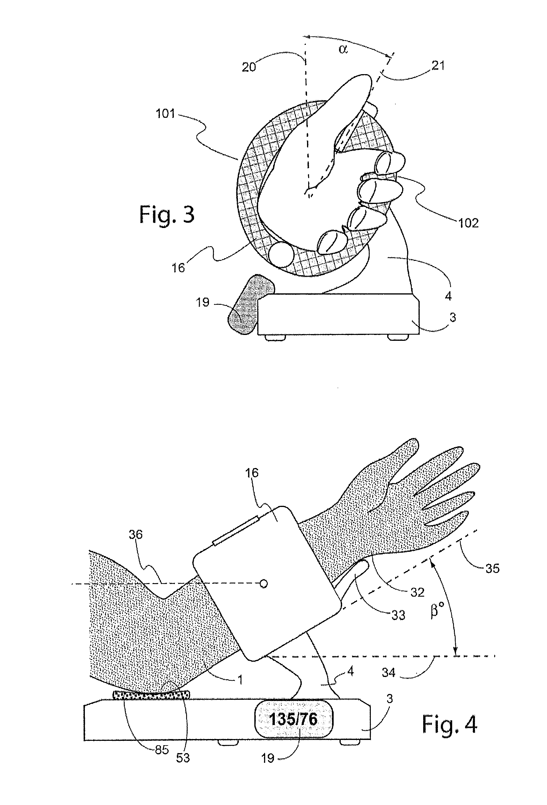
[0025]The present invention relates to non-invasive arterial blood pressure measurement methods using pressurizing cuffs with suitable pressurizing devices (for example, inflatable bladders). Pressure inside the bladder may be generated by a compressed fluid. For example, the compressed fluid may be selected to be air that is compressed and provided to the bladder by a conventional air pump and released from the bladder by a conventional decompression valve). The pressure generated by the bladder is preferably monitored using a pressure sensor coupled to the bladder.

[0026]The oscillometric method described above may be performed by analyzing oscillations in cuff pressure measurements caused by blood surges passing through a pliant artery that transmit pressure pulses to the bladder. The auscultatory method described above may be performed by analyzing the characteristics of acoustic waves (Korotkoff sounds) produced inside the compressed artery. In each case, embodiments of the meth...


PUM


Abstract

A sphygmomanometer with a cuff for use on a patient wrist, upper or lower arm incorporates an inflatable bladder and a support structure. The cuff is subdivided into two sections. The first section holds the bladder against an arterial side of the limb, while the second section abuts a non-arterial side of the limb and is mechanically coupled to the support structure. When the cuff is attached to the patient limb, the bladder is positioned to avoid receiving a gravitational force caused by the weight of the limb. Rather, the gravitational force is absorbed by the support structure in an interior area of the cuff removed from the bladder.

Description

CROSS-REFERENCE TO RELATED APPLICATIONS[0001]This application is a continuation of U.S. application Ser. No. 13 / 505,673, filed May 2, 2012, which was the National Stage of International Application No. PCT / US2009 / 063972, filed on Nov. 11, 2009. The contents of all of these applications are incorporated herein by reference.FIELD OF THE INVENTION[0002]This invention relates generally to methods and medical apparatuses for non-invasive monitoring of arterial blood pressure, and specifically to the devices and methods that use inflatable cuffs.BACKGROUND OF THE INVENTION[0003]Blood pressure monitoring has rapidly become an accepted and, in many cases, essential aspect of human and veterinary treatment. Blood pressure monitors are now a conventional part of the patient environment in emergency rooms, intensive and critical care units, in the operating theater, and in homes.[0004]Several well known techniques have been used to non-invasively monitor a subject's arterial blood pressure wav...

Claims


Application Information

Patent Timeline
Patent Type & Authority Applications(United States)
IPC IPC(8): A61B5/022
CPCA61B5/02233
Inventor FRADEN, JACOBDAVIDSON, JUSTINEWING, WILLIAM
Owner HELEN OF TROY LIMITED
Why Eureka
Try Eureka