
Method and Control Device fort Open-Loop or Closed-Loop Control of a Vehicle Brake System

a technology of brake system and control device, which is applied in the direction of braking system, analogue process for specific applications, instruments, etc., can solve the problems of adverse effects on driving stability and other problems, and achieve the effect of reliable operation of the brake system

Active Publication Date: 2014-07-03
ZF CV SYST EURO BV
View PDF6 Cites 31 Cited by
  • Summary
  • Abstract
  • Description
  • Claims
  • Application Information

AI Technical Summary

Benefits of technology

The present invention provides a method and control device for open-loop or closed-loop control of a brake system that allows for reliable operation with even brake lining wear distribution. This method can also self-learn and improve the selection of the detection method based on subsequent braking operations. Overall, this invention enables better control of braking and improves wear longevity of brakes.

Problems solved by technology

Furthermore, brake lining wear control systems are known for bringing about the most uniform possible brake lining wear at the different wheels or axles.
A relatively large degree of brake lining wear at the axles that have a relatively large axle load is disadvantageous, and therefore, in the case of adhesion-appropriate braking force distributions or brake pressure distributions, such axles are allocated a higher braking force or brake pressure.
For example, in buses, this axle with a tendency to lock is generally the front axle, the locking of which can be perceived as unpleasant by the driver and the passengers; in the case of empty trucks and semitrailer tractors traveling solo, this axle with a tendency to lock is generally the rear axle; driving stability is also adversely affected here.

Method used


Image

  • Method and Control Device fort Open-Loop or Closed-Loop Control of a Vehicle Brake System
  • Method and Control Device fort Open-Loop or Closed-Loop Control of a Vehicle Brake System
  • Method and Control Device fort Open-Loop or Closed-Loop Control of a Vehicle Brake System

Examples


Embodiment Construction

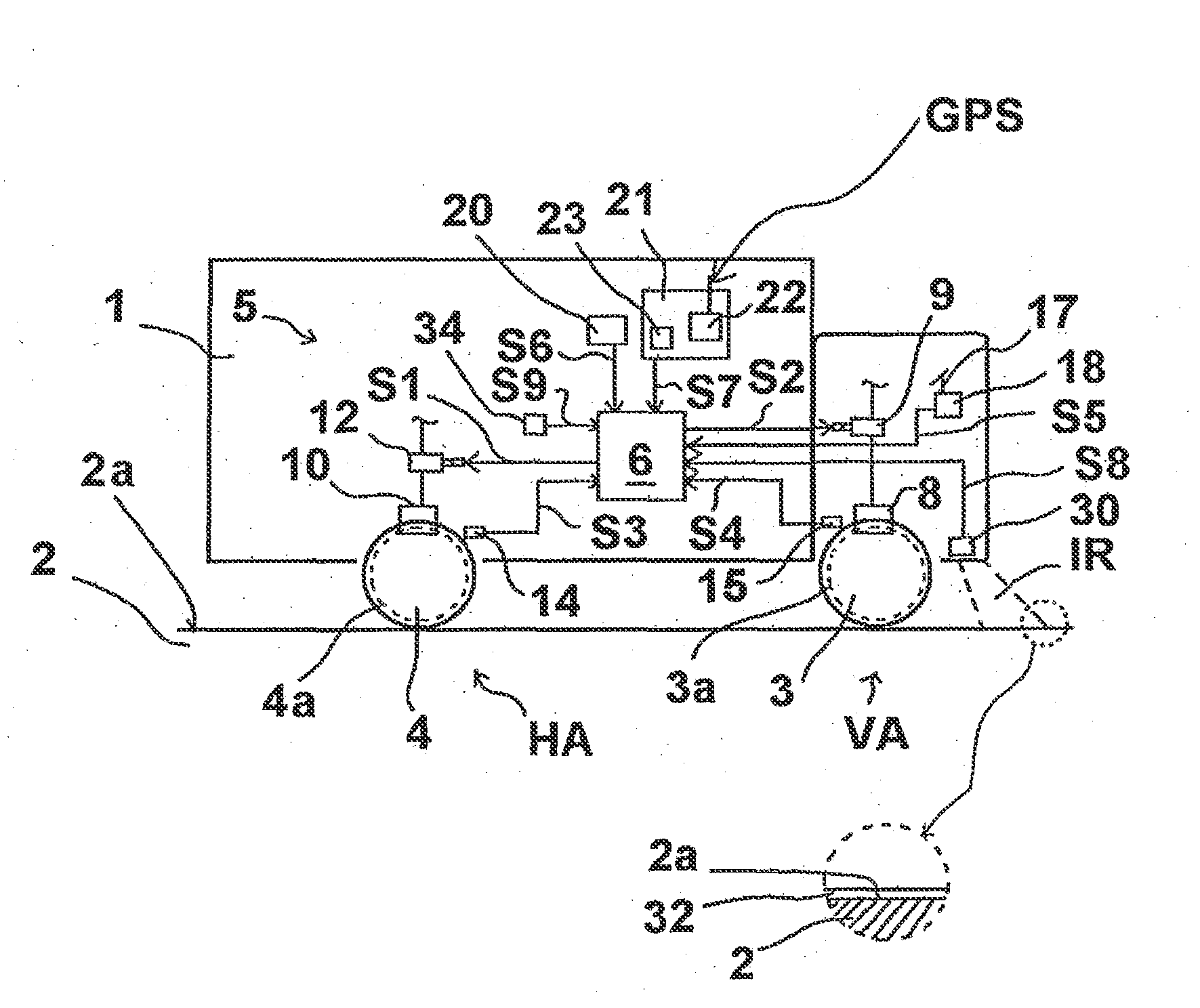
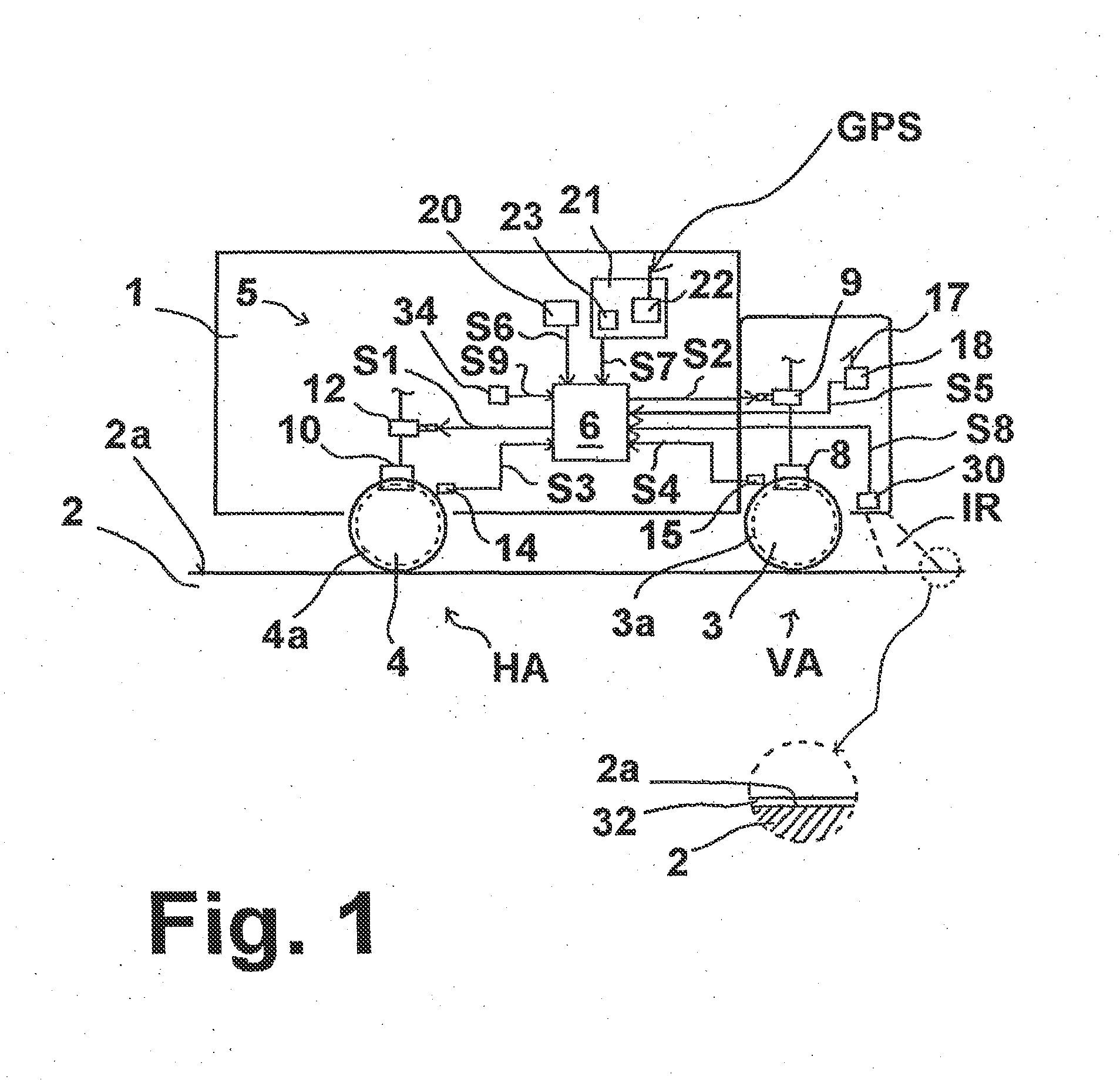
[0079]The vehicle 1, which is embodied as a utility vehicle, travels on a roadway 2 with a roadway surface 2a. The vehicle 1 is shown here by way of example with two axles and has a front axle VA with front wheels 3 and a rear axle HA with rear wheels 4. The front wheels 3 each have a tire surface 3a, and, correspondingly, the rear wheels 4 each have a tire surface 4a, in contact with the roadway surface 2a. The vehicle 1 has a pneumatic brake system 5, which has, inter alia, a control device (ECU) 6, front wheel brakes 8 and electropneumatic brake valve devices 9, rear wheel brakes 10 and electropneumatic brake valve devices 12, as well as rotational speed sensors 34, 15 for outputting rotational speed measurement signals S3, S4. Further components, which are known, can include a compressed air supply system, a multi-circuit valve protection device, and a compressed air accumulator.

[0080]The brake valve devices 9 and 12 are illustrated in simplified form and can also contain relay ...


PUM


Abstract

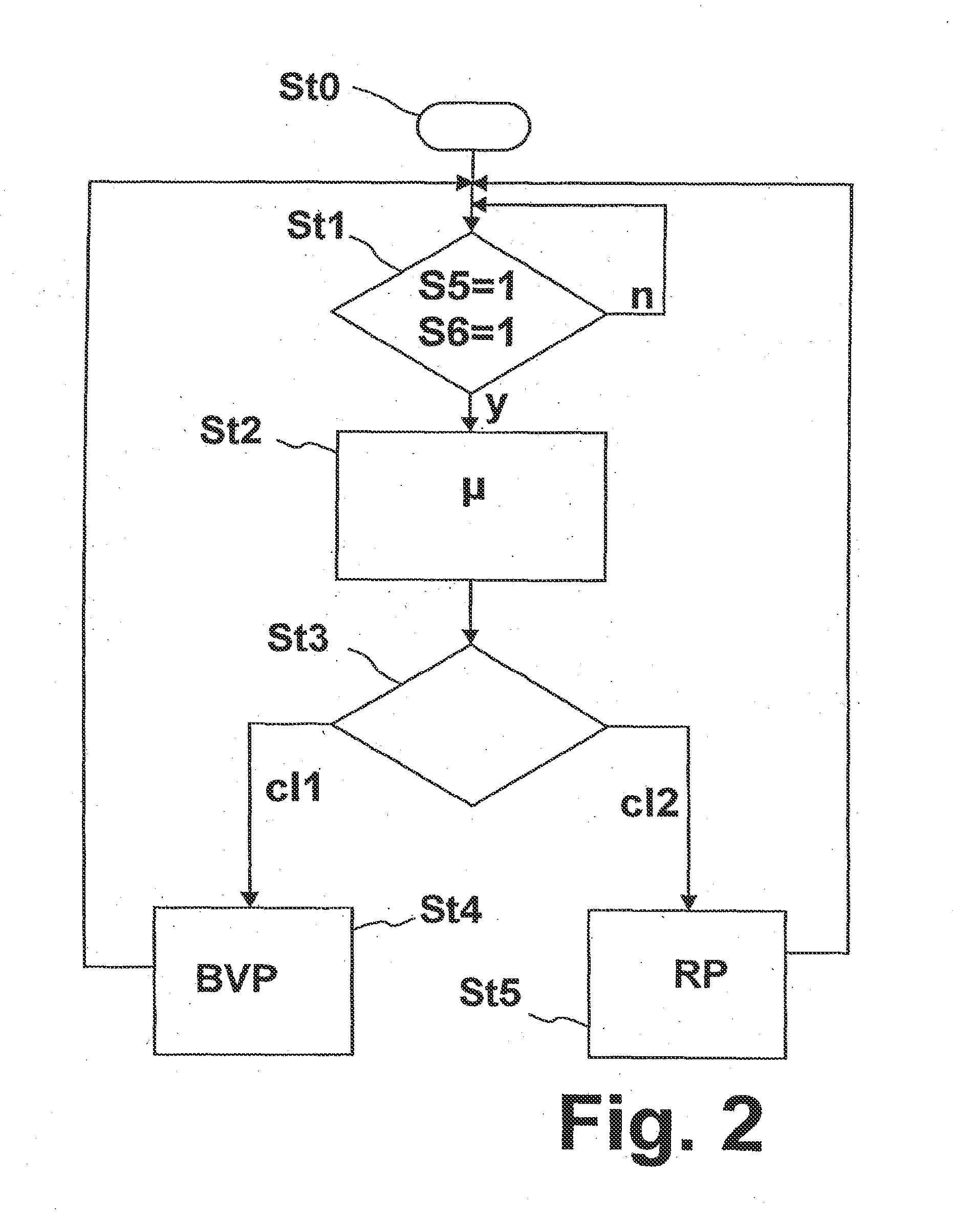
A method for carrying out closed-loop or open-loop control of a vehicle brake system includes, when a braking request signal is present, setting brake pressures at brakes on axles and / or wheels of the vehicle by distributing brake pressure. Before braking is initiated on the basis of current, received or detected data relating to friction conditions or grip conditions between the roadway surface and tire surfaces of the vehicle, a determination is made as to whether, or to what extent, the distribution of brake pressure occurs in a brake wear pressure distribution or in a frictional engagement pressure distribution for the subsequent initiation of the braking process.

Description

FIELD OF THE INVENTION[0001]The invention generally relates to a method and control device for open-loop or closed-loop control of a vehicle brake system.BACKGROUND OF THE INVENTION[0002]DE 10 2008 032 544 A1 describes setting braking forces at the vehicle wheels or axles as a function of brake temperature and of wheel slip values. As a result, braking force distribution takes place on the basis of the slip values, i.e., closed-loop adhesion control.[0003]Different closed-loop control systems are known for brake systems of utility vehicles. Closed-loop slip control systems such as ABS and traction control systems serve to prevent and / or to regulate locking of the braked wheels and spinning of the driven wheels. Driving stability control systems such as ESP and rolling prevention functions serve to prevent skidding and rolling (lateral tipping over) of the vehicle. Longitudinal control systems such as cruise control (CC) functions and adaptive cruise control (ACC) systems relate to a...

Claims


Application Information

Patent Timeline
Patent Type & Authority Applications(United States)
IPC IPC(8): B60T8/172
CPCB60T8/172B60T8/1766B60T8/266B60T2210/12B60T2210/36
Inventor ECKERT, HORSTGAULKE, ARND
Owner ZF CV SYST EURO BV
Learn More