Headgear

a headgear and headband technology, applied in the field of headgear, can solve the problems of eye injury, lack of protection, and high cost of glasses, and achieve the effects of low-tech, low cost and convenient mass production

Inactive Publication Date: 2014-07-10
SNOWRAFT
View PDF8 Cites 8 Cited by
  • Summary
  • Abstract
  • Description
  • Claims
  • Application Information

AI Technical Summary

Benefits of technology

[0008]A further object of the invention is to provide means for reducing the incidence of eye injuries in the course of performing work with abrasive materials and which may eject particulate matter toward the worker.
[0009]Another object is to provide protective headgear that is low-cost and low-tech, making it suitable for mass production and availability.SUMMARY OF INVENTION
[0010]According to the invention, there is provided protective headgear suitable for use in a workplace, the headgear comprising a first, transparent and substantially non-porous membrane having a periphery, means for supporting the first membrane in a vision-facilitating position adjacent the eyes of a wearer in use, a fabric wall comprising a second, flexible and porous membrane, and attachment means attaching the first membrane at the periphery to the wall, wherein the first membrane provides eye protection against particulate projectiles while allowing the wearer to see through it, and the wall provides protection to the wearer against ingress of particulate matter to the wearer's eyes around the periphery of the first membrane.

Problems solved by technology

U.S. Pat. No. 6,880,176 to Timms et al. discloses headgear suitable for equestrian activities, but does not provide for eye protection, concentrating instead on preventing head injuries.
One weakness of safety glasses is that they can tend to lack protection means for particulate matter ricocheting toward the wearer's eyes from above, below and the sides.
Additional side mouldings or shields have been known to be provided with some models, but these add to the cost of these glasses, discouraging purchase, especially by budget-conscious operations.
Another drawback of the above types of safety glasses is that the added side protection means tend to reduce the all-round ability of the glasses to fit all users; one size does not easily fit all.

Method used


Image

  • Headgear
  • Headgear
  • Headgear

Examples


Embodiment Construction

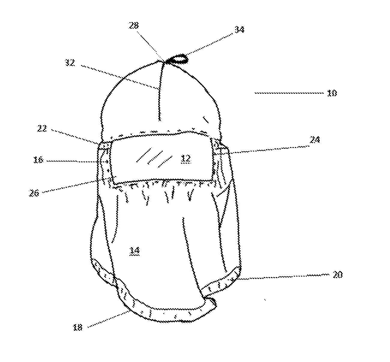
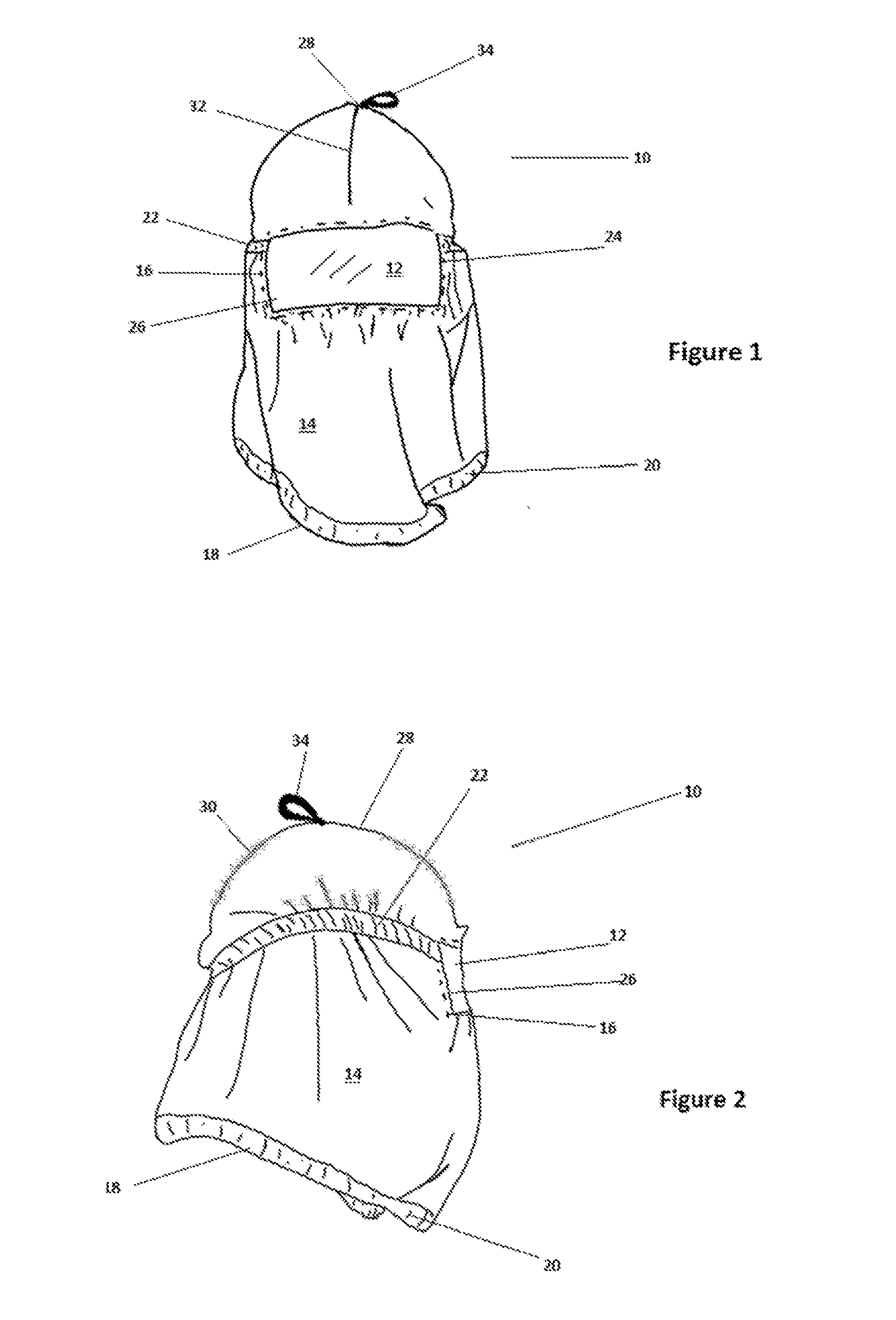
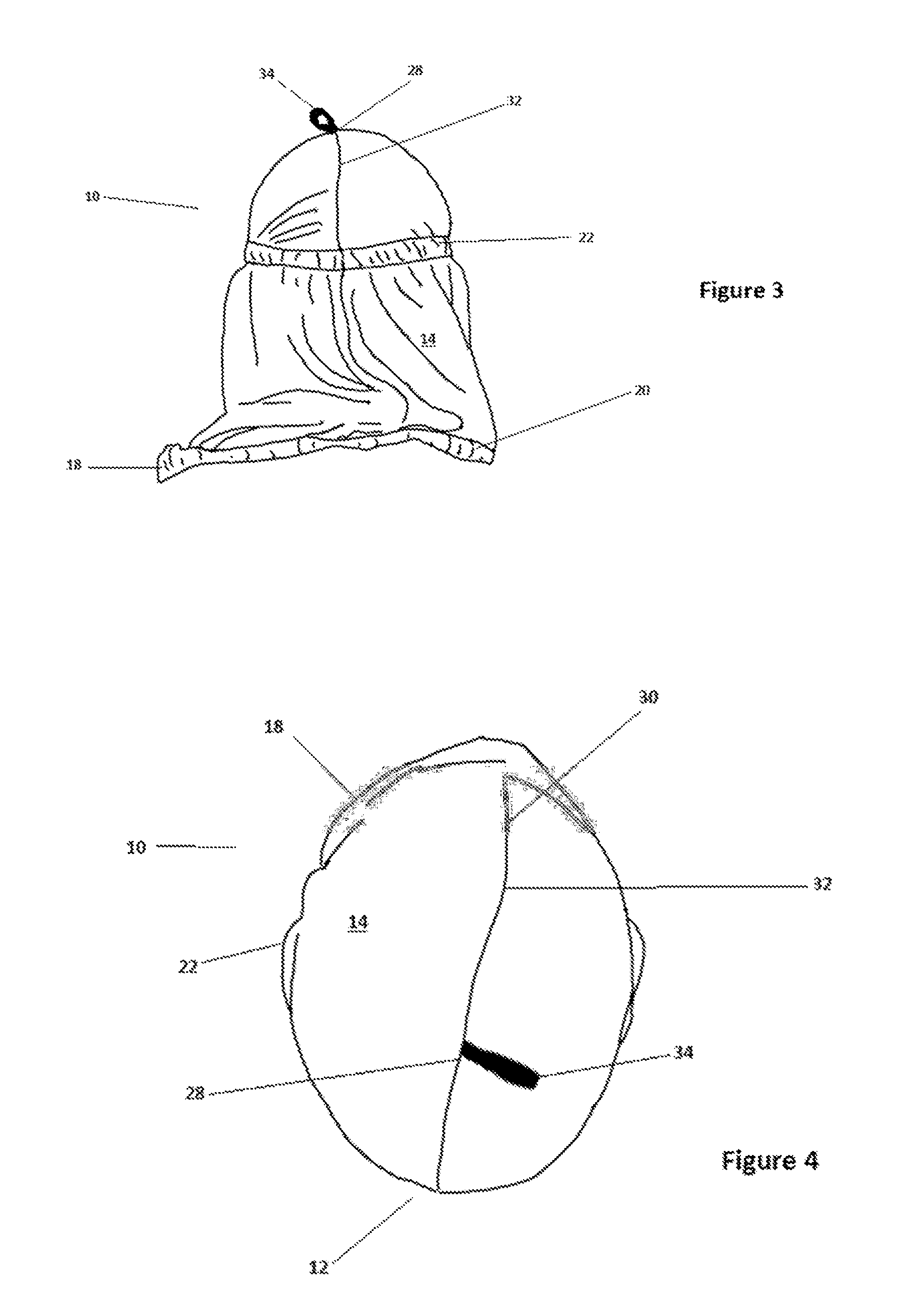
[0053]Referring to FIGS. 1 and 2, an item of protective headgear, according to a preferred embodiment of this invention, is generally denoted by the number 10. It has a transparent membrane of clear polyvinyl-chloride (PVC) 12 surrounded by a fabric wall, defined by a second membrane 14. The wall is adapted to the form of a hood and comprises a single panel of cloth. Membrane 12 is sewn into a correspondingly shaped and sized aperture in the wall as shown by seam 16 (denoted by a broken line), which surrounds it Seam 32 extends over the apex 28 of the headgear and down the rear side at 30, to provide closure for wall 14 to form a hood. In other embodiments, the hood structure may be fabricated from two or more panels of flexible material.

[0054]An eye 34 of a looped strip of textile tape material is attached at the apical region to facilitate hanging of the hood on a suitable peg or nail when not in use In further embodiments, the attachment means for attaching transparent membrane 1...


PUM


Abstract

This invention relates to headgear for protecting the wearer against facial injury, especially eye injury, and in particular eye injury caused by flying particulate matter, such as may be ejected or expelled from a work-piece, the headgear comprising a first, transparent and substantially non-porous eye-protecting membrane and a fabric wall which substantially surrounds the first membrane. The wall is preferably flexible and porous and is attached to the first membrane at its periphery so as to support the first membrane in a vision-facilitating position adjacent the eyes of a wearer in use, wherein the first membrane provides eye protection against particulate projectiles while allowing the wearer to see through it, and the wall provides protection to the wearer against ingress of particulate projectiles from around the transparent first membrane.

Description

PRIORITY CLAIM[0001]This application claims priority to Australian application no. AU 2013900066, filed on Jan. 9, 2013, and to Australian application no AU 2013220865, filed on Aug. 26, 2013, both of which are incorporated herein by reference in their entirety.FIELD OF INVENTION[0002]This invention relates to headgear for protecting the wearer against facial injury, especially eye injury, and in particular eye injury caused by flying particulate matter, such as may be ejected or expelled from a work-piece.BACKGROUND TO THE INVENTION[0003]Many forms of eye protection exist Apart from spectacles and glasses such as industrial safety glasses and sunglasses, there are helmets such as welding helmets, biking helmets, skier helmets, goggles and fire-proof hoods. These have in common a hard protective lens and means for locating and holding in position the lens in effective viewing orientation opposite the eye of the wearer. Not all of these have eye protection as a priority, but more as ...

Claims


Application Information

Patent Timeline
Patent Type & Authority Applications(United States)
IPC IPC(8): A42B3/18
CPCA42B3/18A42B1/247A41D13/1184
Inventor COOMBS, CLYDE KEVIN
Owner SNOWRAFT
Why Eureka
Try Eureka