Method and apparatus for producing progressive waves suitable for surfing using staggered wave generators in sequence

a wave generator and sequence technology, applied in the field of wave pools, can solve the problems of increasing the chance of a wave being wiped out, and the board itself being undesired to be diverted, so as to improve the wave generation and positioning, reduce turbulence and energy loss, and improve the effect of wave quality

Active Publication Date: 2014-07-10
STAGGER REEF PTE
View PDF3 Cites 12 Cited by
  • Summary
  • Abstract
  • Description
  • Claims
  • Application Information

AI Technical Summary

Benefits of technology

[0012]The present invention represents an improvement over previous wave pools comprising multiple wave generators positioned side by side, in that the resultant wave formed by merging the wave segments together is a high quality surfable wave devoid of surface instabilities due to improved wave generation and positioning. The wave pool of the present invention has a relatively deep end and a relatively shallow end, wherein the wave generators are located along the deep end, and the shoreline is located along the shallow end, wherein an inclined shoaling floor extends in-between. But unlike past wave pool designs, in the present invention, the wave generators are preferably oriented at an oblique angle relative to the lateral down-line direction of the resultant waves, and staggered, such that, as the wave generators are operated sequentially, one after the other, the wave segments that are produced merge together to form a smoothly shaped resultant progressive wave suitable for surfing that travels across the wave pool shoaling zone and breaks along the breaker line, with reduced turbulence and loss of energy and minimal reduction in size (height / amplitude), etc.
[0013]Although different configurations are possible, in one embodiment, the wave pool of the present invention is preferably designed in the shape of a parallelogram (as viewed from above) with the wave generators extended along the deep end and the sloped shoaling floor extended up to the shallow end, i.e., where the breaker line is located, wherein the row of wave generators and breaker line are extended substantially parallel to each other. At the same time, both the row of wave generators and breaker line are, in this embodiment, positioned at an oblique angle relative to the moving front or crest of the resultant progressive wave. And, by keeping the sloped floor and wave generators substantially parallel to each other, and allowing the waves to break at an oblique angle relative to the shoreline, the waves that are formed will break obliquely forward and then peel laterally across the width of the pool. Note that the sloped shoaling floor can also consist of horizontal floor sections with one or more stepped up portions that help create the effect of a sloped floor.
[0014]A wave dampening system such as the kind disclosed in Applicant's U.S. Pat. No. 6,460,201, or in U.S. Application Ser. No. 61 / 200,183, which are incorporated herein by reference, is preferably provided along the shallow end to reduce undesirable wave effects such as rip currents and reverse flows, etc., which can adversely affect the breaking of the waves along the shoreline. A standard shoreline that progresses at an incline from the deep end to the shallow water edge, or other sloped beach, can also be provided.

Problems solved by technology

If there are any irregularities in the structure of the wave, such as ridges, angles, ripples, vortices, chops, etc., the wave will be more difficult to maneuver and stay balanced on.
If there is too much turbulence on the surface, for example, or if the smooth portion of the wave is not large or wide enough, the board can lose its planing ability or be diverted, which may cause the surfer to either lose the wave completely, or have to make quick compensating adjustments and corrections, which can increase the chances that he or she will wipe-out by making an erroneous change in body position.
Indeed, one of the significant drawbacks to surfing on a low quality wave is that the board itself can be undesirably diverted, such as, for example, when the tip of the board enters into a chop, in which case, the nose of the board can dive down into the water, which in surf speak is known as ‘pearling’, and will most often result in a wipeout.
One of the shortcomings of traditional wave pools is that they occupy a significant amount of land and therefore are relatively expensive to build.
One serious disadvantage of Leigh, however, is that the wave segments elongate as they follow the angle of the walls, wherein the segments will arc radially outward and eventually interfere with and collide against each other as they converge, rather than merge smoothly to form a uniform periodic wave.

Method used


Image

  • Method and apparatus for producing progressive waves suitable for surfing using staggered wave generators in sequence
  • Method and apparatus for producing progressive waves suitable for surfing using staggered wave generators in sequence
  • Method and apparatus for producing progressive waves suitable for surfing using staggered wave generators in sequence

Examples


embodiment 71

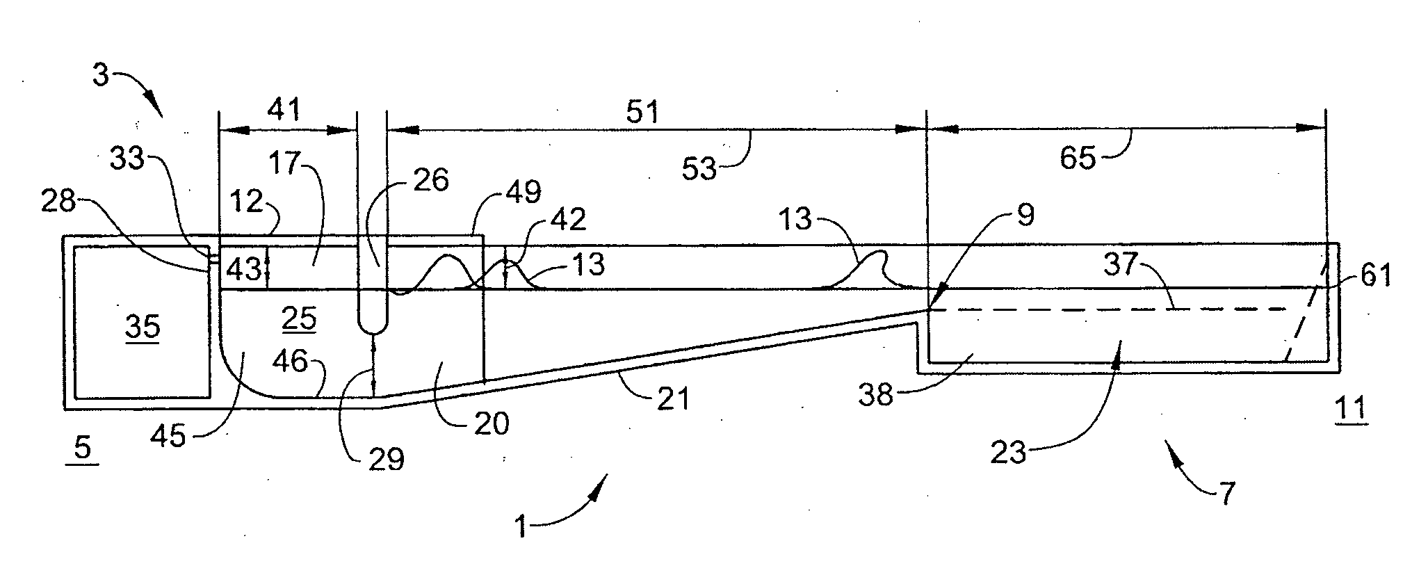
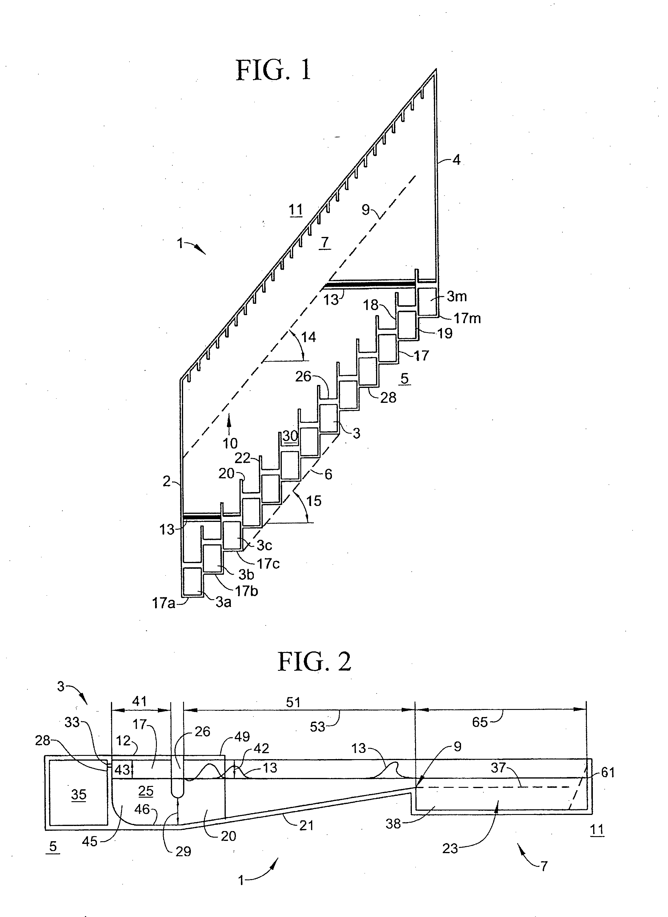
[0093]FIG. 6 shows an alternate embodiment 71 with dividing walls 70, 72 which have a fade angle of up to about 20 degrees or less relative to each other—up to about 10 degrees fade angle on each side. This embodiment is substantially similar to the previous embodiment in that it preferably has wave generators 73 extended along a relatively deep end 75, with an oblique stagger angle extended relative to the front or crest of waves 83. It also preferably has a sloped shoreline 77 that extends along break line 79 that extends substantially parallel to wave generators 73, which results in the peel angle and stagger angle being substantially the same. Another difference is that side walls 74, 76 on either side of pool 71 are preferably extended at about the same angle as dividing walls 70, 72, i.e., although not necessarily so.

[0094]Because of the fade angle that exists between dividing walls 70, 72, it can be seen that wave generators 73 and associated caissons 87 are spaced further ap...

embodiment 1

[0123]When dividing walls 70, 72 have any degree of fade or are off parallel to any extent, wave generators 73 will necessarily be spaced further apart, and therefore, as can be seen in FIG. 6, when the stagger angle is fixed, i.e., such as at 45 degrees, long dividing wall 72 will extend further downstream than long dividing wall 22 of the previous That is, when there is any fade, the dividing walls themselves take up more width across the width of pool 71, and therefore, when caissons 87 are extended at the same stagger angle, i.e., 45 degrees, long dividing wall 72 in front of each caisson 87 will necessarily have to be extended further downstream to make up for the extra width of dividing walls 70, 72. And, in the present case, for purposes of illustration only, the amount by which long dividing wall 72 extends downstream than short dividing wall 70 will be estimated to be about D1 plus one third of D1, which might be the case when the stagger angle is about 45 degrees, and the...


PUM


Abstract

The disclosure relates to a method and apparatus for a wave pool having a deep end and a shallow end, wherein a plurality of wave generators is provided for producing wave segments in the wave pool. The wave generators are preferably extended substantially along the deep end in a substantially staggered manner relative to the travel direction of the wave segments. A pair of dividing walls is preferably provided in front of each wave generator, wherein the dividing walls are extended substantially forward in the travel direction and substantially parallel to each other or with a fade angle of no more than about 20 to 30 degrees relative to each other. The wave generators are preferably operated in sequence from one side of the pool to the other, such that a plurality of wave segments is generated at pre-selected time intervals, and such that the plurality of wave segments can travel forward and then, due to the stagger of the wave generators, merge together to form a substantially uniform resultant periodic wave. The resultant wave forms and travels forward and then breaks along the shallow end which preferably comprises a break line.

Description

FIELD OF THE INVENTION [0001]The present invention relates to the field of wave pools, and in particular, to a wave pool that comprises using multiple staggered wave generators in sequence with dividing wall extensions for enhanced performance that enable wave segments to be formed and merged together to form a single progressive wave that breaks along an obliquely angled sloped shoreline.BACKGROUND OF THE INVENTION[0002]The art of surfing requires a combination of natural ability, practice and skill. It requires making continual adjustments to the surfer's balance, to keep a large longitudinally oriented surfboard skimming across the surface of the water traveling forward at just the right velocity and angle, such that the wave can propel the board and surfer forward, while at the same time, the surfer is able to lean and make adjustments to carve out a path at just the right moment, and with just the right directional feet pressure and body English. It is essentially a careful bal...

Claims


Application Information

Patent Timeline
Patent Type & Authority Applications(United States)
IPC IPC(8): E04H4/00
CPCE04H4/0006A63B69/0093A63B2208/03
Inventor LOCHTEFELD, THOMAS J.BASTENHOF, DIRK
Owner STAGGER REEF PTE
Why Eureka
Try Eureka