Efficient chiller for a supercritical fluid chromatography pump

Active Publication Date: 2014-07-10
AGILENT TECH INC
View PDF14 Cites 30 Cited by
  • Summary
  • Abstract
  • Description
  • Claims
  • Application Information

AI Technical Summary

Benefits of technology

[0032]Since the function of the first pump is simply to raise the pressure of the fluid, and the second pump exclusively meters the flow, any effect of supply cylinder temperature and pressure and booster pump head temperature on mass flow rate is eliminated. The actual temperature of the chiller is immaterial as long as the fluid exists as a liquid in the booster, although lower temperature allows the pump to deliver the same required mass with fewer strokes. By separating the functions of compression and metering to two different pumps, flow noise is greatly reduced. These are major advantages over all previous SFC pumping schemes.
[0033]The act of compression from 60 bar to 400 bar can raise the temperature of carbon dioxide as much as 25° C. Provision is also made in the present invention to pass the fluid exiting the pump through an additional heat exchanger to remove the heat of compression from the fluid before it is transferred to the metering pump. In one embodiment a second flow plate is included in the same chiller plate for this function

Problems solved by technology

Separating the two tasks means that the condenser temperature becomes relatively unimportant, since its

Method used


Image

  • Efficient chiller for a supercritical fluid chromatography pump
  • Efficient chiller for a supercritical fluid chromatography pump
  • Efficient chiller for a supercritical fluid chromatography pump

Examples


Embodiment Construction

[0043]It will be readily understood that the components of the present invention, as generally described and illustrated in the Figures herein, may be arranged and designed in a wide variety of different configurations. Thus, the following detailed description of the embodiments of the apparatus, system, and method of the present invention, as presented in the Figures, is not intended to limit the scope of the invention, as claimed, but is merely representative of selected embodiments of the invention.

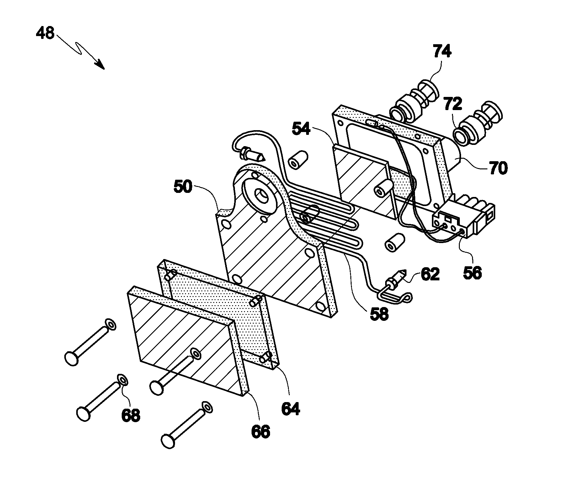
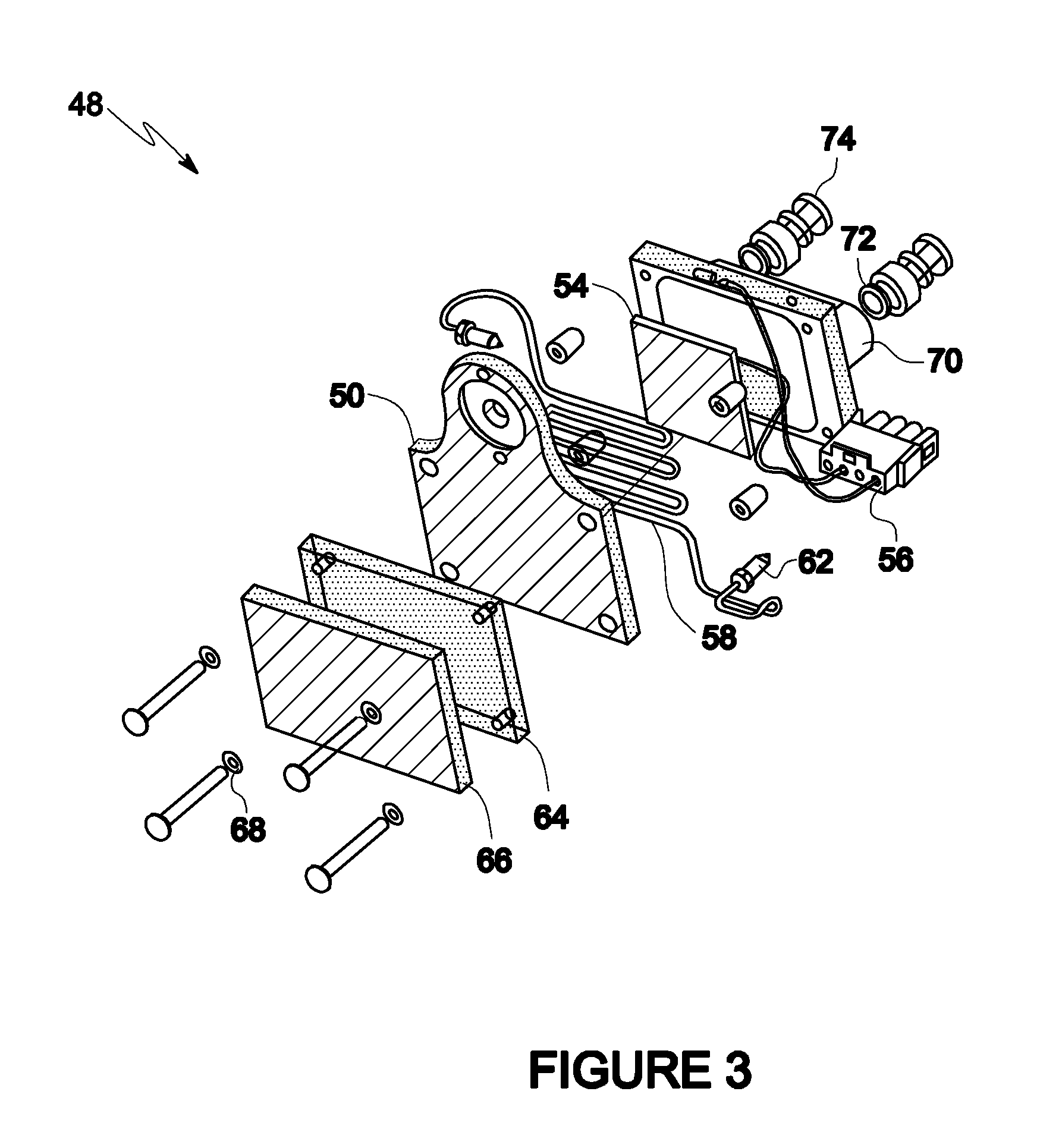
[0044]Referring to FIGS. 4, 5, and 6, a schematic illustration of a representative pump head chiller assembly 48 is displayed. A cold plate or chiller plate 50 is attached to a Peltier element 54 with associated electrical connectors 56. The chiller plate 50 is formed out of copper but could be aluminum or other appropriate materials. Chiller plate 50 is mounted near or behind a pump head through plate extension 52. In one embodiment, the chiller plate 50 is mounted perpendicular to th...


PUM


Abstract

Methods and systems for pumping compressible fluids in high pressure applications such as high-pressure liquid chromatography (HPLC) or supercritical fluid chromatography (SFC) applications are disclosed. An improved cooling device for a pump head for use in a supercritical fluid chromatography (SFC) system is described. A system for chilling a pumping system, includes a Peltier cooling element in thermal contact with a pump head, wherein the cooling element chills the pump head and a mobile phase fluid flowstream prior to the mobile phase fluid entering the pump; a fluid-cooled heat exchanger, attached to the Peltier cooling element, which removes heat from the cooling element using a circulating fluid; and a second heat exchanger which cools the circulating fluid.

Description

[0001]The present application is a U.S. national phase application under 35 USC §371(c) of International Application Pub. No. WO / 2011 / 149456 filed on May 26, 2010, naming T. Berger and K. Fogelman as inventors. The entire disclosure of International Application Pub. No. WO / 2011 / 149456 is hereby incorporated by reference in its entirety.FIELD OF THE INVENTION[0002]The present invention relates to methods and systems for pumping compressible fluids. More specifically, it relates to pumping compressible fluids in high pressure applications such as high-pressure liquid chromatography (HPLC) or supercritical fluid chromatography (SFC) applications.BACKGROUND[0003]Industrial pumping takes many forms, all with the general requirement of transporting fluids or slurries through a process stream. Pumps are selected based on the application requirements including head pressure, metering accuracy, temperature, particle tolerance, fluid viscosity, cost, safety, service rate and a variety of othe...

Claims


Application Information

Patent Timeline
IPC IPC(8): F25B21/02
CPCF25B21/02B01D15/40F04B39/064F04B53/08G01N2030/326B01D15/12F25B21/04
Inventor BERGER, TERRY A.FOGELMAN, KIMBER
Owner AGILENT TECH INC
Why Eureka
Try Eureka