Balancer device of internal combustion engine
a technology of internal combustion engine and balancer, which is applied in the direction of machines/engines, mechanical equipment, vibration suppression adjustments, etc., can solve the problems the complexity of the work of engaging the gears with the scissors gear, and achieve the effect of increasing the cost of the balancer devi
- Summary
- Abstract
- Description
- Claims
- Application Information
AI Technical Summary
Benefits of technology
Problems solved by technology
Method used
Image

Examples
embodiment 1
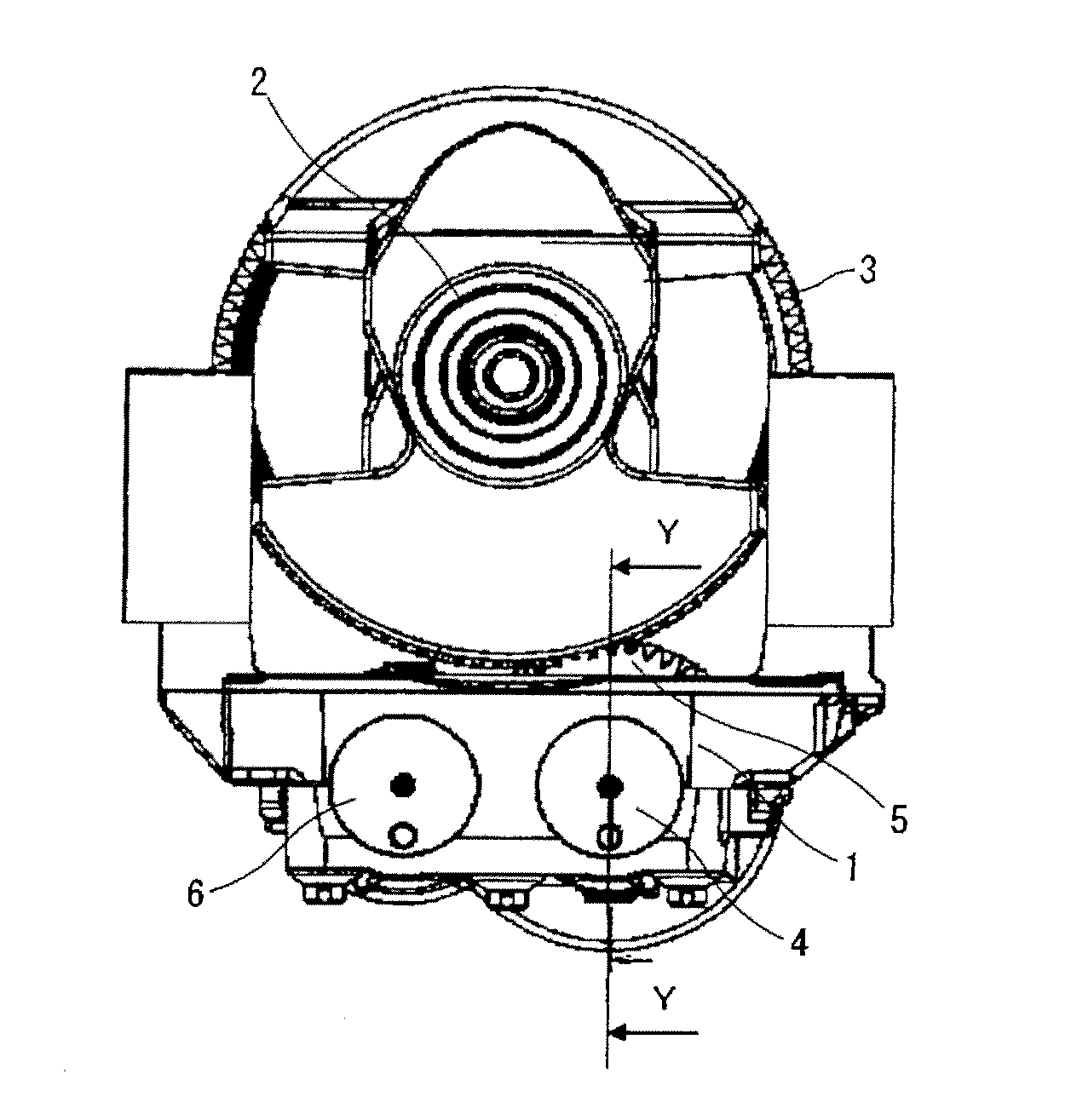
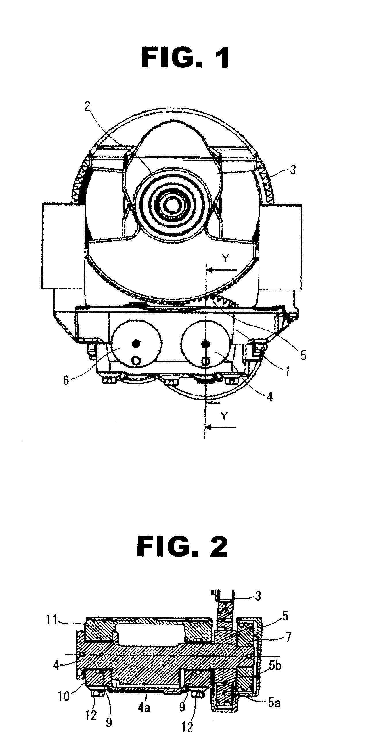
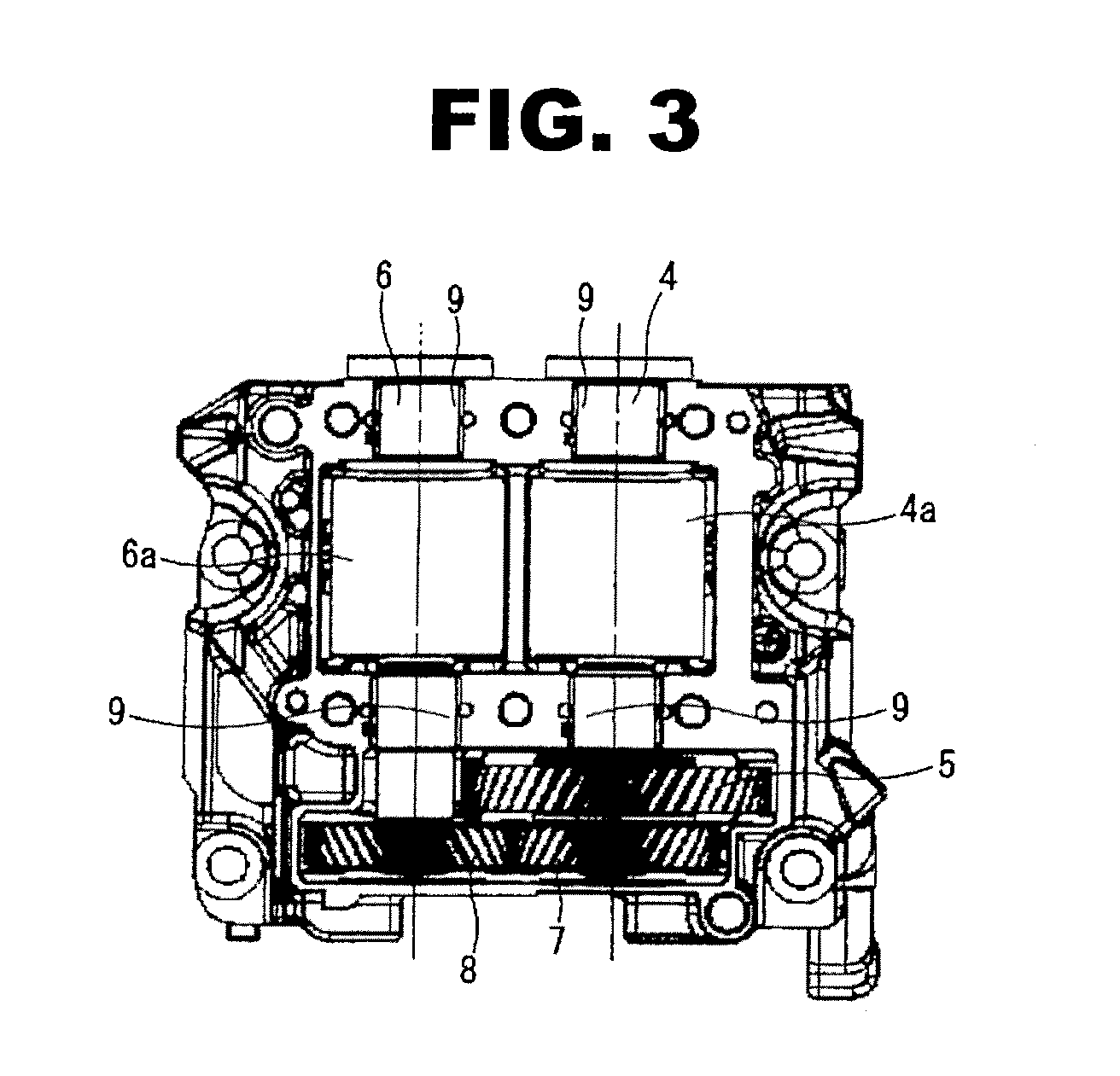
[0022]FIG. 1 is a front view of the balancer device mounted in an engine. FIG. 2 is a sectional view, taken along a Y-Y line of FIG. 1, of the balancer device. FIG. 3 is a drawing when viewing a housing unit from its bottom with a lower housing removed.
[0023]As shown in FIG. 1, a balancer device 1, which is rotated and driven by a crank gear 3 that is fixed to a crankshaft 2, is provided on a lower surface of a cylinder block (not shown) of the internal combustion engine.
[0024]As shown in FIGS. 1 to 3, the balancer device 1 has a main gear (a drive gear) 5 to which a rotation force from the crank gear (an input gear) 3 is transmitted by being engaged with the crank gear 3, a balancer drive shaft 4 to which a rotation force from the main gear 5 is transmitted, a balancer drive gear 7 which is fixed to the balancer drive shaft 4, a balancer driven gear 8, each tooth of which is engaged with each tooth of the balancer drive gear 7, and a balancer driven shaft 6 to which a rotation forc...
embodiment 2
[0056]FIG. 5 is a sectional view of the main gear 5 of the balancer device 1 according to an embodiment 2. In the following embodiments, components or structures except the ring-shaped grooves 5a and 5b of the main gear 5 are the same as those of the embodiment 1, therefore their explanations will be omitted here.
[0057]As shown in FIG. 5, in the embodiment 2, elastic members 13 that have the substantially same shape as the ring-shaped grooves 5a and 5b are inserted in the ring-shaped grooves 5a and 5b so that an elastic force or an expansive force of the elastic members 13 acts on inner and outer circumferences of the ring-shaped grooves 5a and 5b. The elastic member 13 is formed from material that absorbs the vibrations such as rubber and resin or damping steel.
[0058]According to the balancer device 1 of the present embodiment 2, as compared with the embodiment 1, since the elastic member 13 absorbs the vibrations which are sources of the noise and suppresses the transmission of th...
embodiment 3
[0059]FIG. 6 is a sectional view of the main gear 5 of the balancer device 1 according to an embodiment 3. As shown in FIG. 6, in the embodiment 3, instead of the elastic member 13 of the embodiment 2, O-rings 14 which are low-priced vibration absorbing members are inserted in the ring-shaped grooves 5a and 5b so that an elastic force or an expansive force of the O-rings 14 acts on the inner and the outer circumferences of the ring-shaped grooves 5a and 5b.
[0060]According to the balancer device 1 of the present embodiment 3, as same as the embodiment 2, since the O-ring 14 absorbs the vibrations which are sources of the noise and suppresses the transmission of the vibrations, the noise / vibration performance can be further improved. Further, by using the low-priced O-ring 14 as the vibration absorbing member, it is possible to reduce the cost.
PUM
 Abstract
Description
Claims
Application Information
 - R&D
- Intellectual Property
- Life Sciences
- Materials
- Tech Scout
- Unparalleled Data Quality
- Higher Quality Content
- 60% Fewer Hallucinations
Browse by: Latest US Patents, China's latest patents, Technical Efficacy Thesaurus, Application Domain, Technology Topic, Popular Technical Reports.
© 2025 PatSnap. All rights reserved.Legal|Privacy policy|Modern Slavery Act Transparency Statement|Sitemap|About US| Contact US: help@patsnap.com