Automatic welding apparatus for end plug of nuclear fuel rod

Active Publication Date: 2014-07-10
KEPCO NUCLEAR FUEL CO LTD
View PDF26 Cites 13 Cited by
  • Summary
  • Abstract
  • Description
  • Claims
  • Application Information

AI Technical Summary

Benefits of technology

[0016]In the automatic welding apparatus used to perform resistance welding on the cladding tube and the end plug in the welding chamber in accordance with the present invention, the cladding tube clamp transfers the cladding tube toward the welding chamber using the servo motor. The end plug welding electrodes transfer the end plug fed from an end

Problems solved by technology

Thus, to manufacture the nuclear fuel assembly, many fuel rods are required, and

Method used


Image

  • Automatic welding apparatus for end plug of nuclear fuel rod
  • Automatic welding apparatus for end plug of nuclear fuel rod
  • Automatic welding apparatus for end plug of nuclear fuel rod

Examples


Example

[0023]Reference will now be made in greater detail to an exemplary embodiment of the present invention with reference to the accompanying drawings.

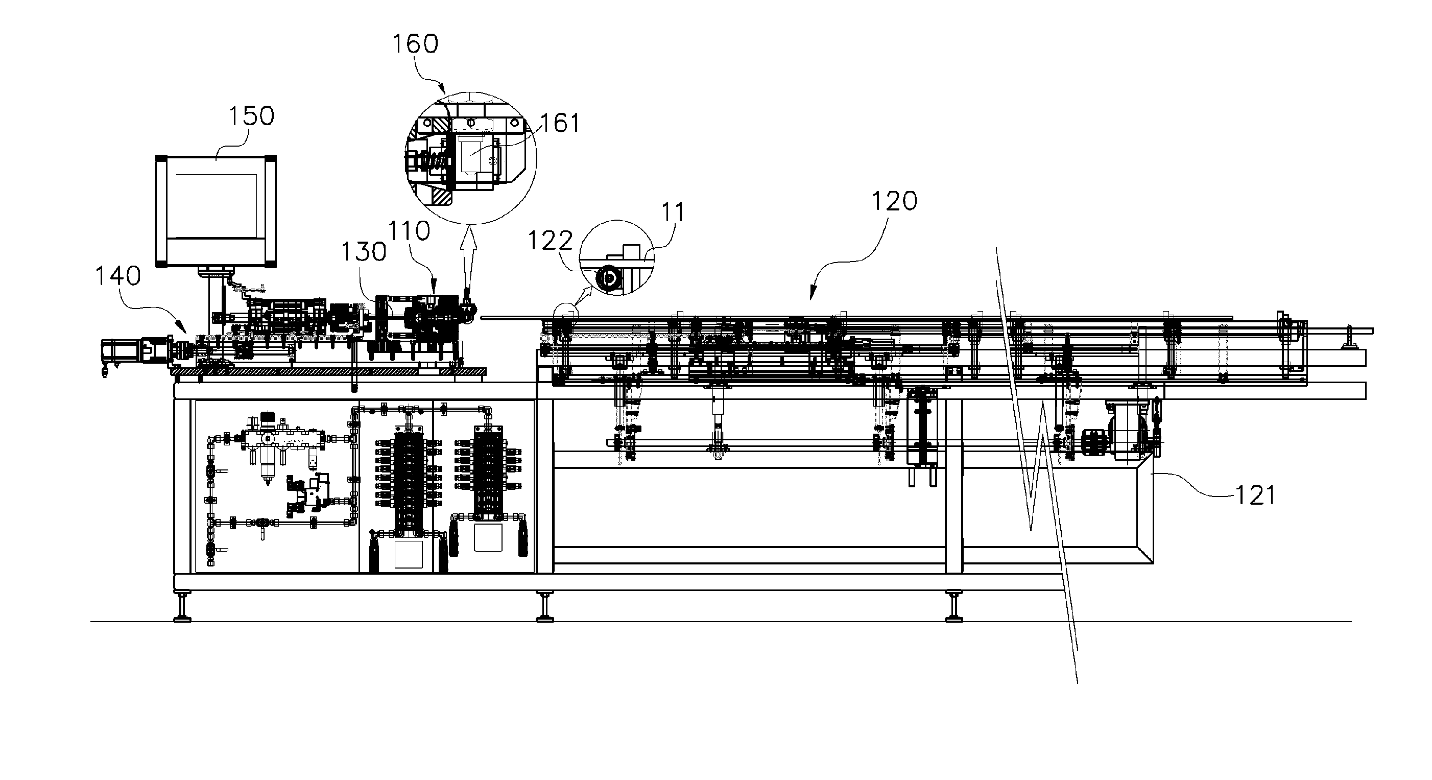
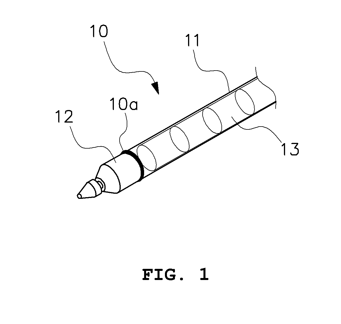
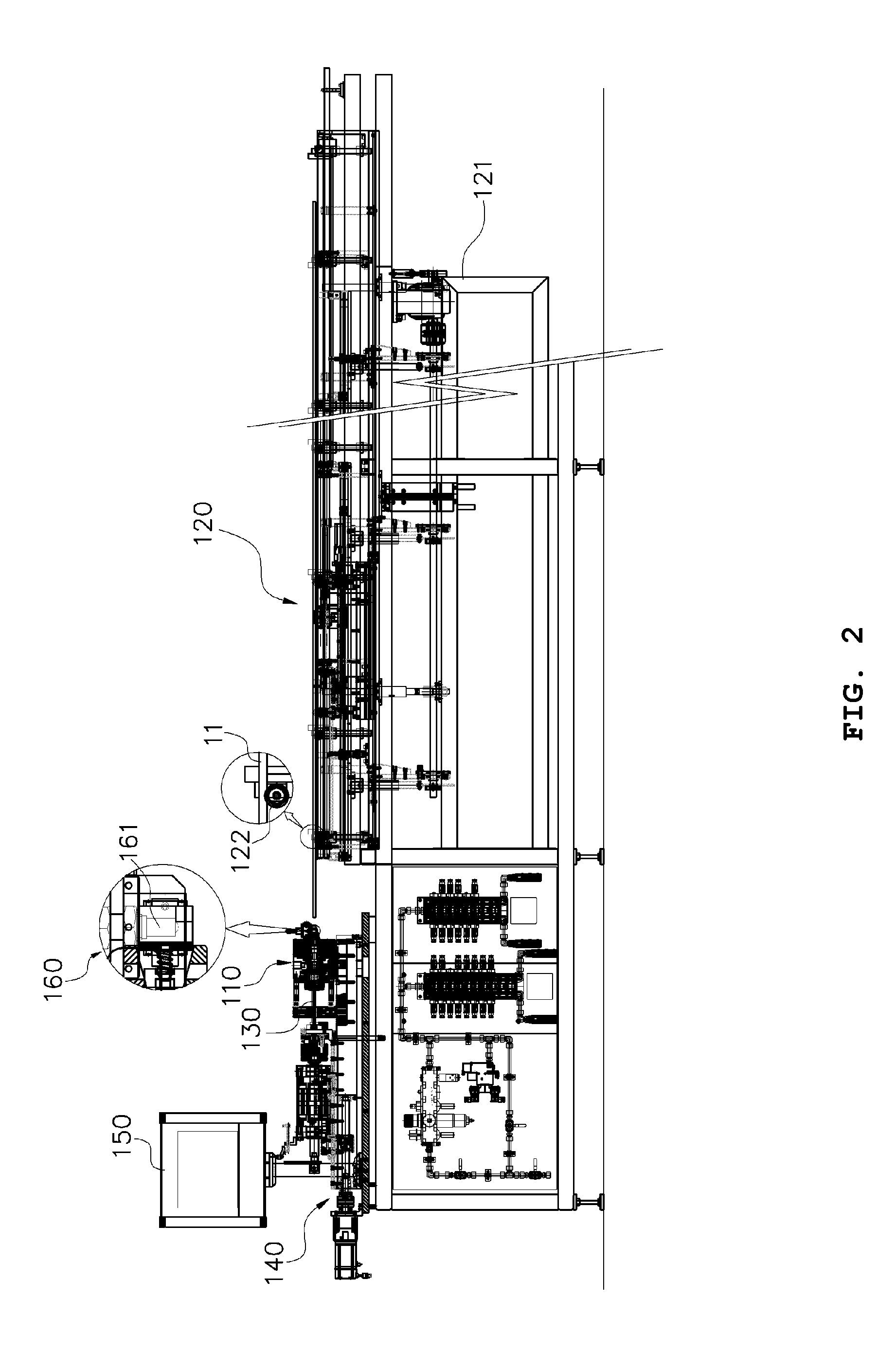
[0024]An automatic welding apparatus for an end plug of a nuclear fuel rod according to an embodiment of the present invention includes: to perform resistance welding on a cladding tube and the end plug in a welding chamber, the welding chamber 110 configured to perform the resistance welding on the end plug 12 and the cladding tube 11; a cladding tube transfer unit 120 that has a cladding tube clamp 123 fixedly clamping the cladding tube 11 and a first servo motor 124 for driving the cladding tube clamp 123 in a horizontal direction and that horizontally transfers the cladding tube to the welding chamber 110; end plug welding electrodes 130 gripping the end plug 12 fed from an end plug feeder; an end plug transfer driver 140 for driving the end plug welding electrodes 130 toward the welding chamber 110 in a forward / backward direction; an...


PUM

PropertyMeasurementUnit
Timeaaaaaaaaaa

Abstract

Disclosed is an automatic welding apparatus for an end plug of a nuclear fuel rod, which is used to perform resistance welding on a cladding tube and the end plug in a welding chamber. The automatic welding apparatus includes a welding chamber configured to perform resistance welding on an end plug and a cladding tube, a cladding tube transfer unit that has a cladding tube clamp fixedly clamping the cladding tube and a first servo motor for driving the cladding tube clamp in a horizontal direction and that horizontally transfers the cladding tube to the welding chamber, end plug welding electrodes gripping the end plug fed from an end plug feeder, an end plug transfer driver for driving the end plug welding electrodes toward the welding chamber in a forward/backward direction, and a position control module for controlling driving of the first servo motor and the end plug transfer driver.

Description

BACKGROUND OF THE INVENTION[0001]1. Field of the Invention[0002]The present invention relates to an automatic welding apparatus for an end plug of a nuclear fuel rod and, more particularly, to an apparatus for automatically welding a cladding tube and an end plug constituting a nuclear fuel rod in an accurate and rapid way using a servo motor.[0003]2. Description of the Related Art[0004]Nuclear reactors are facilities for artificially controlling a fission chain reaction of a fissionable material to use thermal energy generated from nuclear fission as power.[0005]Nuclear fuel used in the nuclear reactor is manufactured by forming concentrated uranium into uniformly sized cylindrical pellets (hereinafter referred to as “sintered compacts”) and then charging a plurality of sintered compacts in a fuel rod. This plurality of fuel rods constitutes a nuclear fuel assembly, wherein the fuel rods are loaded in a reactor core, and are then burnt by a nuclear reaction.[0006]Referring to FIG. ...

Claims


Application Information

Patent Timeline
IPC IPC(8): G21C21/02
CPCG21C21/02B23K11/00B23K11/36B23K11/093B23K37/047Y02E30/30B23K31/02G21C3/10
Inventor CHO, YOUNG CHOONHWANG, CHANG HWANCHANG, HUNG SOONKONG, SANG PILNA, TAE HYUNGYOON, YOUNG SEOK
Owner KEPCO NUCLEAR FUEL CO LTD
Why Eureka
Try Eureka