Check patentability & draft patents in minutes with Patsnap Eureka AI!

Dual-mode switching power control device

Inactive Publication Date: 2014-07-10
INNOTECH CO LTD
View PDF2 Cites 8 Cited by
  • Summary
  • Abstract
  • Description
  • Claims
  • Application Information

AI Technical Summary

Benefits of technology

The present invention improves the efficiency of power conversion by reducing switching loss in light loading and conduction loss in heavy loading. This results in a more effective use of power and is suitable for higher power applications.

Problems solved by technology

However, one shortcoming in the prior arts is that higher current spikes and RMS (root-mean-square) values are caused in QR flyback converters operating in DCM.
It thus results in higher conduction loss and turn-off switching loss in heavy loading such that the efficiency of power conversion is reduced.
Therefore, QR flyback converters operating in DCM are not suitable for higher power applications.
Additionally, current power converters use various fixed preset modes or only one mode as the operating mode, and it is not possible to adjust or change the operating mode or operating parameters for different electric transformers and other elements such that the best efficiency is attained.

Method used


Image

  • Dual-mode switching power control device
  • Dual-mode switching power control device
  • Dual-mode switching power control device

Examples


Embodiment Construction

[0019]The present invention may be embodied in various forms and the details of the preferred embodiments of the present invention will be described in the subsequent content with reference to the accompanying drawings. The drawings (not to scale) show and depict only the preferred embodiments of the invention and shall not be considered as limitations to the scope of the present invention. Modifications of the shape of the present invention shall too be considered to be within the spirit of the present invention.

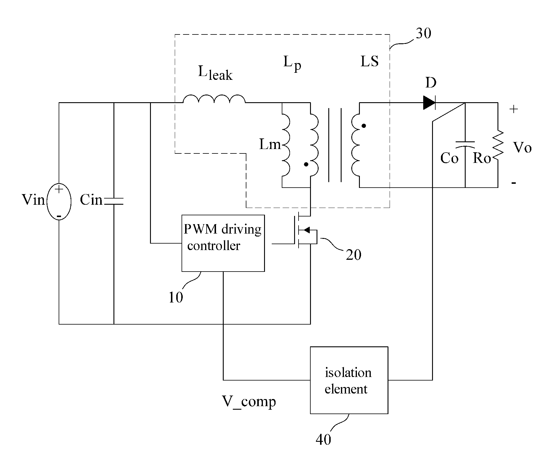
[0020]FIG. 1 illustrates a dual-mode switching power control device according to the present invention. As shown in FIG. 1, the dual-mode switching power control device of the present invention generally includes a PWM (pulse width modulation) driving controller 10, a switching transistor 20, an electric transformer 30, an isolation element 40, an output diode D and an output capacitor Co. The present invention implements the function of converting an input power with an in...


PUM


Abstract

A dual-mode switching power control device includes an electric transformer, a PWM driving controller, a switching transistor, an isolation element, an output diode and an output capacitor. The PWM driving controller is connected to the switching transistor coupled to the electric transformer. The first side inductor of the electric transformer and the switching transistor are coupled to an input power, and the second side inductor of the electric transformer is coupled to the output diode. The output capacitor and a load are connected in series. The output power is converted into a feedback signal by the isolation element. The PWM driving controller determines to perform DCM or CCM based on the feedback signal to control the current flowing through the electric transformer, and the output power is generated. Therefore, the efficiency of power conversion is improved and is suitable for high power applications.

Description

CROSS-REFERENCE TO RELATED APPLICATION[0001]This application claims the priority of Taiwanese patent application No. 102100582, filed on Jan. 8, 2013, which is incorporated herewith by reference.BACKGROUND OF THE INVENTION[0002]1. Field of the Invention[0003]The present invention relates to a control device for power conversion, and more specifically to a dual-mode switching power control device that dynamically controls a flyback converter to perform DCM (Discontinuous Conduction Mode) or CCM (Continuous Conduction Mode) based on a loading state.[0004]2. The Prior Arts[0005]Different electronic devices require specific electric power to operate. For example, ICs (integrated circuits) are supplied with 5V, 3V or 1.8V, electric motors need 12V DC, and high power devices require 110V or 220V AC, like city power. In particular, the lamp of the LED display usually operates at even much higher voltage. Thus, many kinds of electric converters have been developed to meet those various dema...

Claims


Application Information

Patent Timeline
IPC IPC(8): H02M3/335
CPCH02M3/33515H02M3/33523H02M1/0032Y02B70/10
Inventor LIN, CHING-YUANLIN, SHU-CHIALIN, CHIH FENG
Owner INNOTECH CO LTD
Features
  • R&D
  • Intellectual Property
  • Life Sciences
  • Materials
  • Tech Scout
  • Unparalleled Data Quality
  • Higher Quality Content
  • 60% Fewer Hallucinations
Learn More