Device for localizing hot spots with heat flow meters

a technology of heat flow meter and hot spot, which is applied in the direction of heat measurement, thermometer using value differences, instruments, etc., can solve the problems of degrading certain physical and electrical characteristics of electronic devices, affecting the operation of surveyed electronic components, and general invasiveness of temperature sensors, etc., and achieves high integration density.

Active Publication Date: 2014-07-10
COMMISSARIAT A LENERGIE ATOMIQUE ET AUX ENERGIES ALTERNATIVES
View PDF11 Cites 12 Cited by
  • Summary
  • Abstract
  • Description
  • Claims
  • Application Information

AI Technical Summary

Benefits of technology

[0008]In certain applications using electronic devices formed with a high integration density on a substrate surface, a non-invasive, reliable, and easy-to-form system, enabling to locate and to quantify the temperature of a hot spot which appears in this surface of the substrate, is thus needed.

Problems solved by technology

Such a phenomenon may cause the degradation of certain physical and electrical characteristics of electronic devices.
Thus, the temperature sensor is generally invasive, that is, it is formed within the surveyed area which comprises the critical electronic components.
In particular, in the case of a diode-type temperature sensor, the current flow in the diode may disturb the operation of the surveyed electronic component.
Accordingly, this type of temperature sensors is formed according to specific methods, which further complicates their manufacturing.
Such an arrangement of the temperature sensors is difficult to achieve since it depends on several factors, such as the available surface area of the package substrate and the layout of the electric connections connecting the temperature sensors and the thermal power management circuit.
Further, such a device has a very small observation area, and it is incapable of detecting a difficult-to-access hot spot.
The forming of this type of heat regulation device then becomes complicated.

Method used


Image

  • Device for localizing hot spots with heat flow meters
  • Device for localizing hot spots with heat flow meters
  • Device for localizing hot spots with heat flow meters

Examples


Embodiment Construction

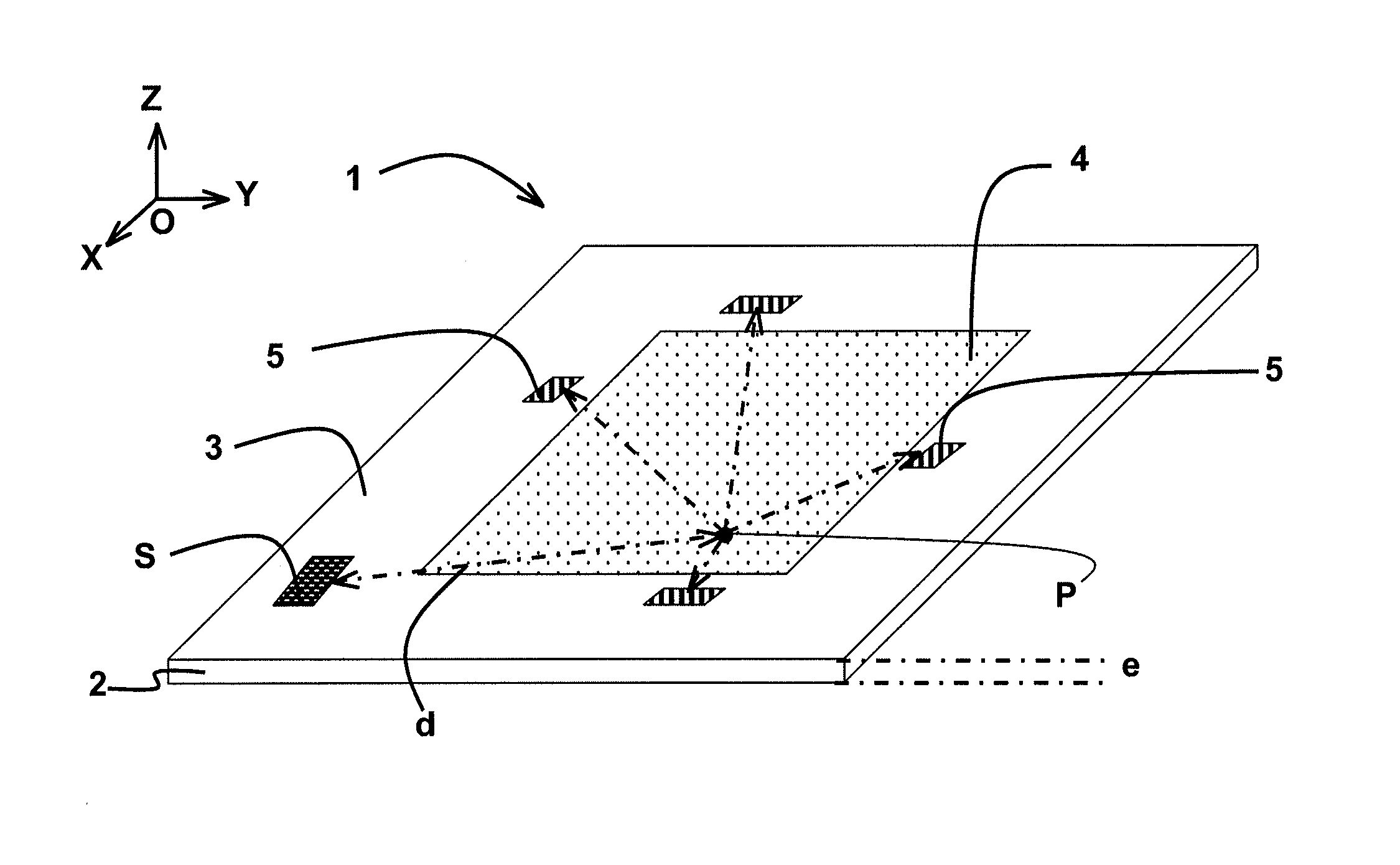
[0017]A practical and reliable way to detect hot spots in a region of interest of a substrate surface comprises using a system based on heat flow meters. More specifically, the hot spot detection system is a non-invasive system which comprises heat flow meters arranged outside of the region of interest having a thermal behavior to be monitored.

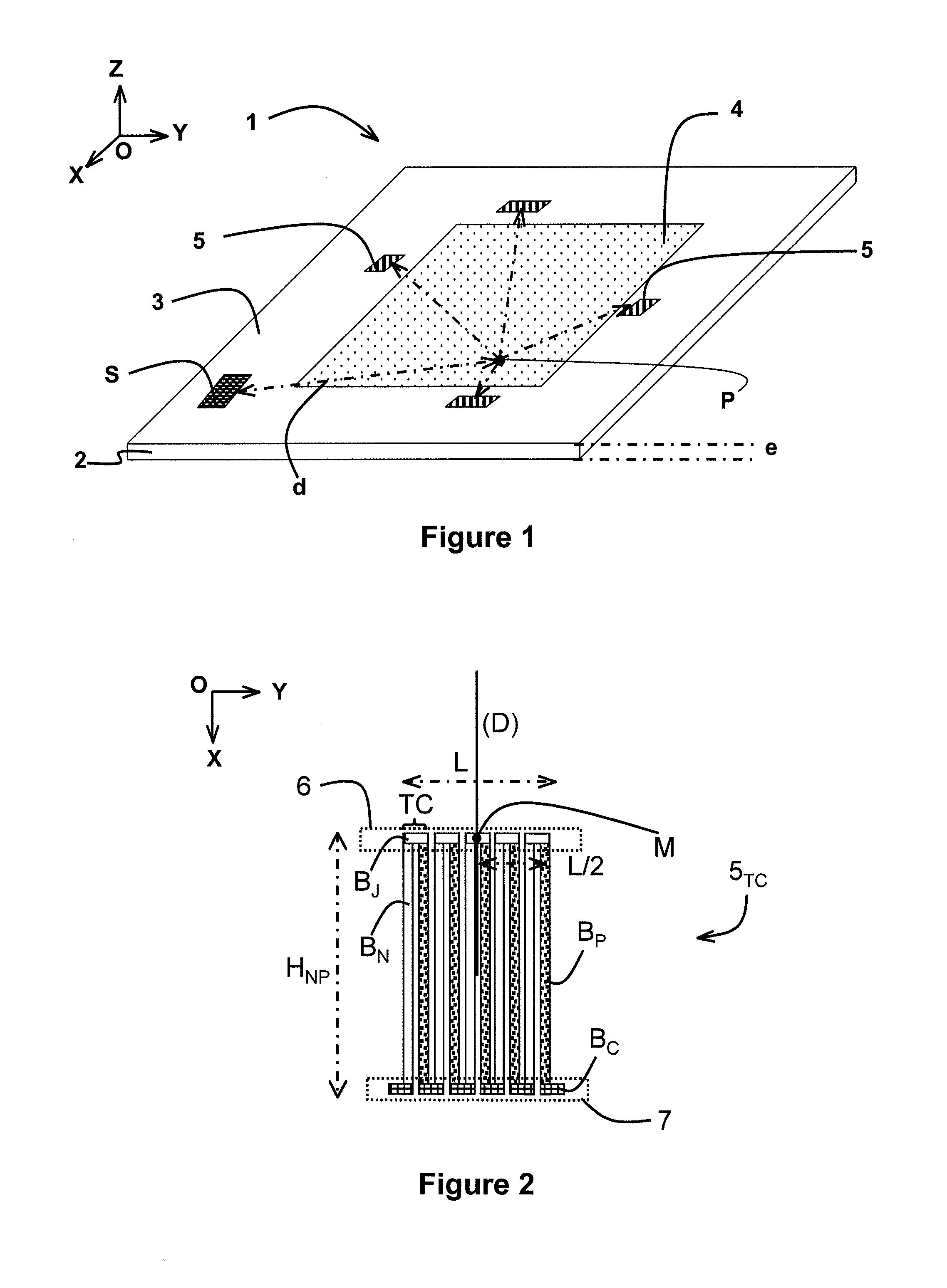
[0018]According to a specific embodiment, electronic device 1 is shown in FIG. 1. Electronic device 1 comprises a substrate 2, preferably having a thickness e. Substrate 2 is provided with a surface 3, preferably substantially planar, and comprising a region of interest 4 having a thermal behavior to be monitored.

[0019]Region of interest 4 of substrate 2 may for example comprise one or several active or passive components formed on the front surface of substrate 2, that is, on surface 3. These components, by dissipating a given electric power, may cause a temperature rise in the region of interest, thus creating a hot spot. “Monitoring” means ...


PUM

PropertyMeasurementUnit
temperatureaaaaaaaaaa
thermoelectricaaaaaaaaaa
direction angleaaaaaaaaaa

Abstract

The electronic device comprises a substrate provided with a surface comprising a region of interest, the thermal behavior of which is to be monitored, and a system for detecting hot spots located in the region of interest. The system for detecting hot spots comprises at least three separate heat flow meters arranged on the surface of the substrate outside of the region of interest.

Description

BACKGROUND OF THE INVENTION[0001]The invention relates to a device comprising a region of interest arranged on a surface of a substrate and a system for detecting hot spots located in said region of interest.STATE OF THE ART[0002]As the integration density increases, the electric power dissipated within electronic devices never stops growing. The increase of the dissipated electric power may generate a so-called self-heating phenomenon. Such a phenomenon may cause the degradation of certain physical and electrical characteristics of electronic devices.[0003]Currently, electronic circuits comprise more and more thermal power management systems. When the temperature within the electronic circuit exceeds a given threshold, the thermal power management system may for example start a fan or suspend the activity of certain components or secondary circuits. The efficiency of this type of system depends on the information collected by a temperature sensor, relative to the heating condition ...

Claims


Application Information

Patent Timeline
Patent Type & Authority Applications(United States)
IPC IPC(8): G01K1/14
CPCG01K1/143H01L23/34H01L23/38H01L2924/0002G01K7/427G01K2003/145H01L2924/00
Inventor CAROFF, TRISTANREMONDIERE, VINCENT
Owner COMMISSARIAT A LENERGIE ATOMIQUE ET AUX ENERGIES ALTERNATIVES
Why Eureka
Try Eureka