
Fenestrated bone screw and method of injecting bone cement into bone structure

a bone screw and bone cement technology, applied in the field of fenestration pedicle bone screws, can solve the problems of lessening the purchase of bone screws in such bone structures, reducing bone quality, and reducing bone quality

Active Publication Date: 2014-07-10
POULOS NICHOLAS
View PDF2 Cites 17 Cited by
  • Summary
  • Abstract
  • Description
  • Claims
  • Application Information

AI Technical Summary

Benefits of technology

The patent describes a method of injecting bone cement into bone structures using a plurality of bone screws with a cannula and open fenestrations. The method involves connecting a cement delivery tube to each screw, connecting a cement pump to the delivery tube, injecting cement into the screws, and removing the cement pump without leaking cement. The technical effect is a reliable and safe method for delivering bone cement into bone structures during spine surgeries.

Problems solved by technology

In many instances, particularly in spine surgeries, the patient may have diminished or osteoporotic bone quality, which lessens the purchase of bone screws in such bone structure.
In spine surgery, such diminished bone quality oftentimes precludes stabilization of the vertebrae and leads to pedicle screw loosening and pullout.
Unfortunately these screws are expensive and sub-optimally perform in biologically challenged osteoporotic bone.
While screw loosening and the tendency of the screw to pull out of the bone are reduced, percutaneous screw placement is not possible and thus kyphoplasty cannot be used with minimal invasive surgery (MIS) platforms.
Further, once the screw is placed, it cannot be repositioned if the screw is inserted along an unsatisfactory trajectory.
Still further, if multi-level fixation is required, such kyphoplasty augmented screw placement would require multiple kyphoplasty kits (e.g., balloons and injection systems) that would make the procedure prohibitively expensive.
While such prior cannulated / fenestrated screw and cement injection systems have worked for their intended purpose, deficiencies have been found.
The coupling and uncoupling of the cement injection system to the screw head of such screw bone cement augmentation systems has been problematic.
Typically, the attachment of the cement injection cannula to the screw head has not been mechanically secure such that the surgeon oftentimes was required to hold the cement injection cannula docked to the screw head and to monitor for cement leakage Particularly in MIS procedures, the screw head is not visible to the surgeon such that it is difficult to reversibly mechanically connect the cement injection cannula to the screw head.
This bone core would block or occlude the flow of cement in the main channel of the screw and would block the flow of cement to the fenestrations or side bores effectively rendering the desired function useless.
As a result, in such prior cannulated / fenestrated pedicle screws, the location of the injected bone cement is potentially along the posterior half of the screw in the posterior of the vertebrae, which is a far from optimal because of the potential extravasation of the bone cement into the spinal canal and foramen.

Method used


Image

  • Fenestrated bone screw and method of injecting bone cement into bone structure
  • Fenestrated bone screw and method of injecting bone cement into bone structure
  • Fenestrated bone screw and method of injecting bone cement into bone structure

Examples


Embodiment Construction

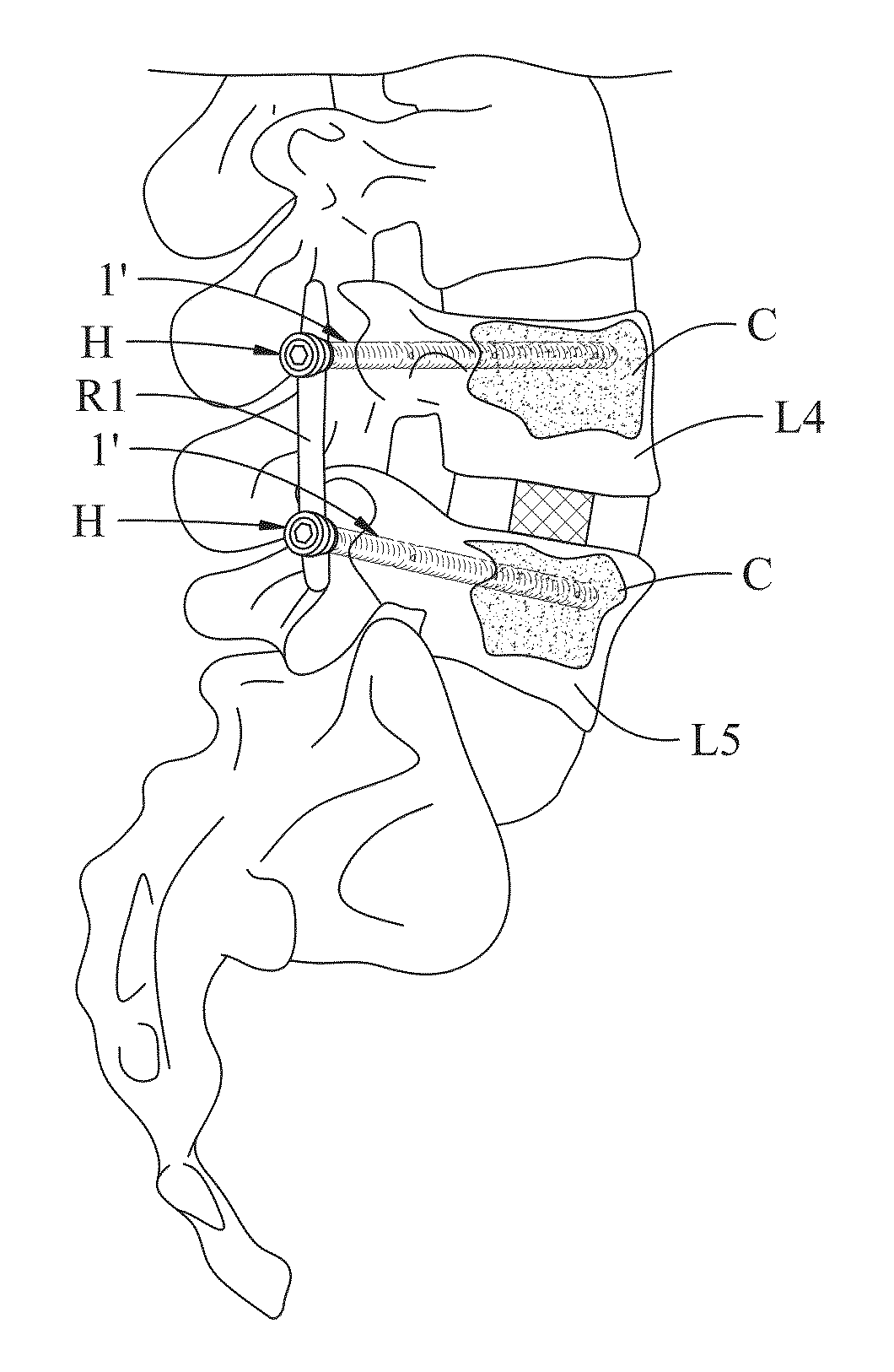
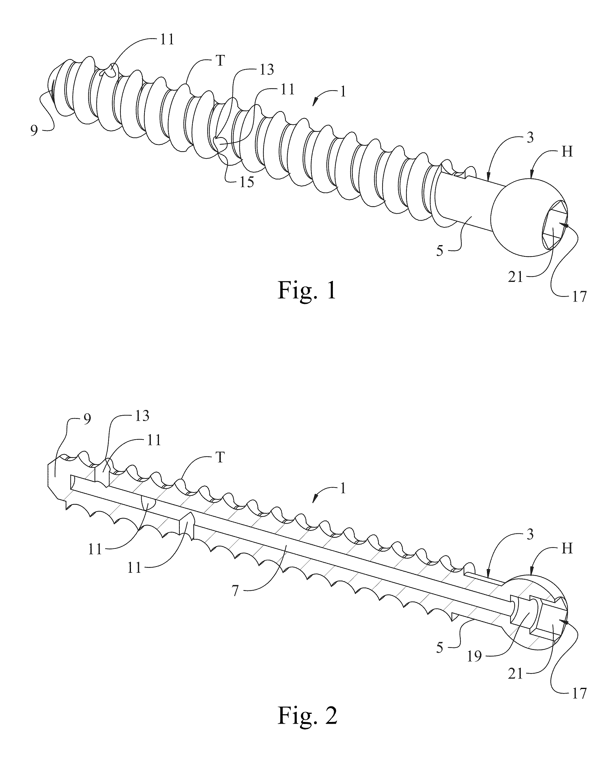
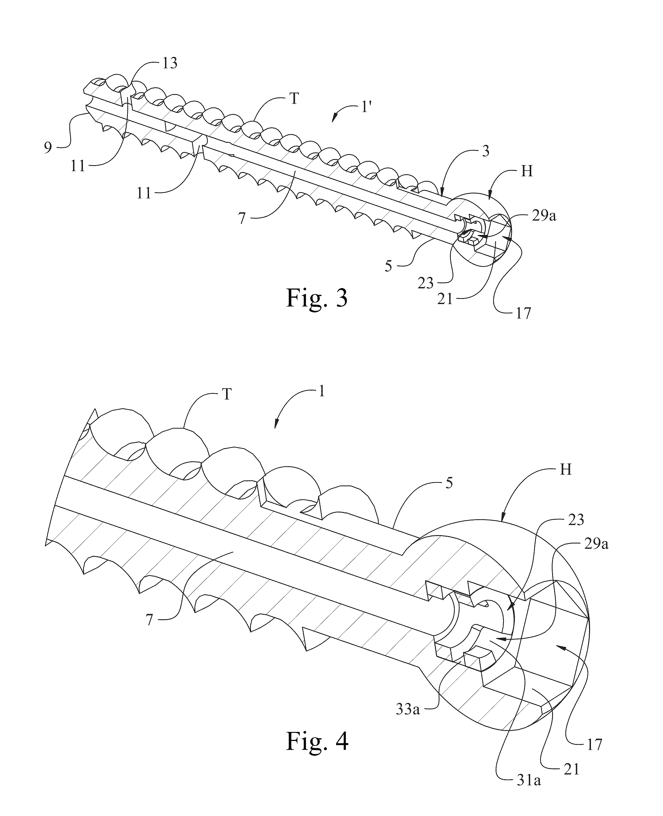
[0048]Referring now to FIG. 1, a fenestrated / cannulated bone screw of the present disclosure, and more particularly a pedicle screw, is illustrated in its entirety by reference character 1. Screw 1 has a part-spherical head H for the attachment of a poly-axial saddle (not shown) that is conventionally used in spinal surgery. However, those skilled in the art will recognize that heads H of different designs, shapes, and purposes may be used in conjunction with the screw of the present disclosure. Screw 1 has a shank, as generally indicated at 3, having bone threads T formed or machined on a substantial length of the shank. As indicated at 5, the portion of the shank proximate head H may be free of threads T, however, the threads may extend proximate the head H.

[0049]More particularly, screw 1, as shown in FIG. 2, is a blind end cannulated screw having a cannula 7 extending from head H to the distal end of the screw, but where the cannula 7 does not extend through the tip 9 of the scr...


PUM


Abstract

A fenestrated bone screw and method of use is disclosed in which a bone cement injection tube may be readily and sealably connected to the head of the bone screw by means of a bayonet connector so that bone cement from a cement pump may be forced into a cannula of the bone screw and into the bone structure proximate the fenestrations of the bone screw. Upon completion of the injection of the bone cement, the cement tube may be readily disconnected from the bone screw in such manner that leakage of bone cement is minimized. A surgical method of injecting bone cement into bone structure using such a cannulated, fenestrated bone screw is also disclosed.

Description

CROSS-REFERENCE TO RELATED APPLICATIONS[0001]This application claims priority to U.S. Provisional Patent Application No. 61 / 750,131, filed on Jan. 8, 2013, which is herein incorporated by reference in its entirety herein.STATEMENT REGARDING FEDERALLY SPONSORED RESEARCH OR DEVELOPMENT[0002]Not ApplicableBACKGROUND OF THE DISCLOSURE[0003]This disclosure relates to fenestrated bone screws, and in particular to fenestrated pedicle bone screws, and to methods of installing such fenestrated bone screws in a variety of surgeries, particularly spine surgeries, and to the methods of injecting bone cement (e.g., polymethyl methacrylate (PMMA), or the like) into the proximate bone structure into which such fenestrated screws are installed.[0004]In many instances, particularly in spine surgeries, the patient may have diminished or osteoporotic bone quality, which lessens the purchase of bone screws in such bone structure. In spine surgery, such diminished bone quality oftentimes precludes stabi...

Claims


Application Information

Patent Timeline
Patent Type & Authority Applications(United States)
IPC IPC(8): A61B17/70A61B17/86
CPCA61B17/8822A61B17/7098A61B17/864
Inventor POULOS, NICHOLAS
Owner POULOS NICHOLAS
Learn More