
Percutaneous osseointegrated implant assembly for use in supporting an exo-prosthesis

a technology of osseointegration and implant assembly, which is applied in the field of implant assembly, can solve the problems of amputees not being able to consistently use their prosthetics, limited use of prosthetics, and increasing the susceptibility of amputees to additional co-morbidities, so as to improve proprioception, reduce dermatological complications, and be easy to install

Active Publication Date: 2014-07-10
UNIV OF UTAH RES FOUND
View PDF5 Cites 18 Cited by
  • Summary
  • Abstract
  • Description
  • Claims
  • Application Information

AI Technical Summary

Benefits of technology

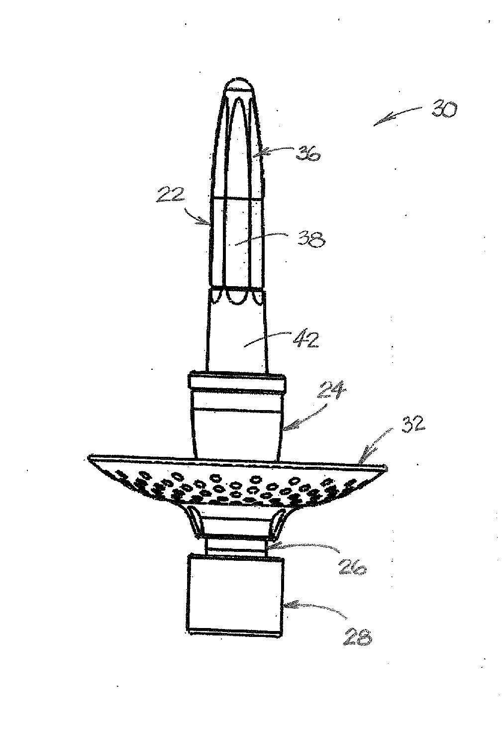
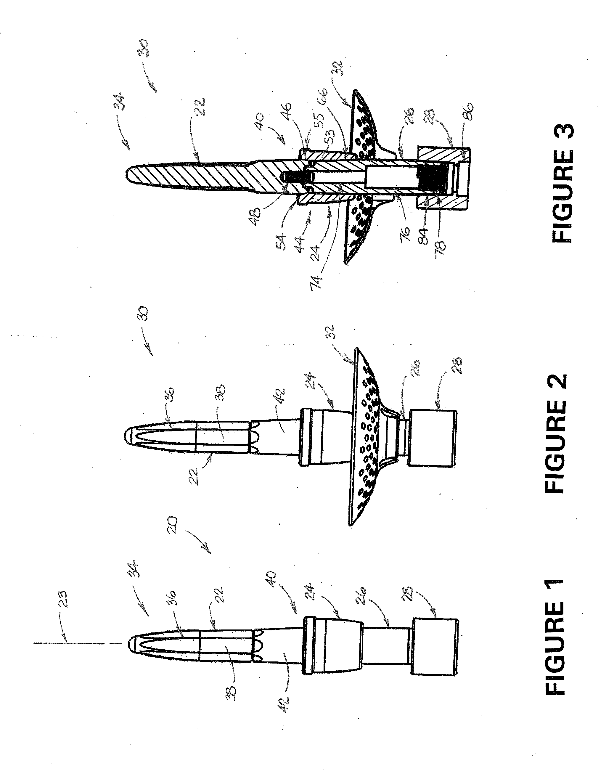
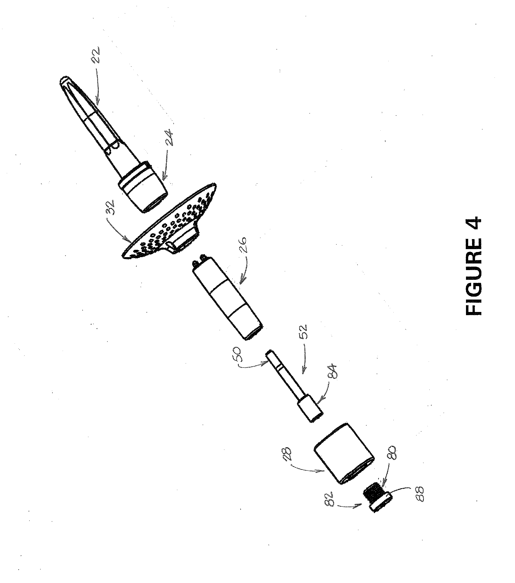
The invention is an implant assembly for replacing a long bone with an exo-prosthesis. It consists of a stem, a subdermal component, and a percutaneous post. The stem is designed to be inserted into the bone marrow canal and promote bone growth. The subdermal component attaches to the stem and is designed to fit through a cut in the bone. The percutaneous post connects to the subdermal component and helps to secure the implant in place. The invention helps to provide a stable and secure implant for long bones requiring replacement.

Problems solved by technology

The inability of these amputees to consistently use their prosthetics represents a significant decrease in their quality of life.
In lower limb amputees, the limitations on usage of a prosthetic increase the susceptibility of the amputees to additional co-morbidities.
High infection rates remain a major limitation of current prosthetic systems.
A high infection rate is often associated with the lack of a skin seal at the skin-implant interface that provides an ideal direct path for opportunistic bacterial invasion to the stomal tissue and often results in sinus tract formation.
This may subsequently result in deep infection and bone loss requiring implant removal.
Because of the rapid evolution of antibiotic-resistant pathogens as well as the high incidence of methicillin-resistant Staphylococcus aureus (MRSA) cases, these infections may not be treatable with conventional antibiotic therapy.
Commonly, the outcome is device removal and further loss of bone and soft tissue resulting in shortening of the residual limb.

Method used


Image

  • Percutaneous osseointegrated implant assembly for use in supporting an exo-prosthesis
  • Percutaneous osseointegrated implant assembly for use in supporting an exo-prosthesis
  • Percutaneous osseointegrated implant assembly for use in supporting an exo-prosthesis

Examples


Embodiment Construction

[0036]The following description of the invention is provided as an enabling teaching of the invention in its best, currently known embodiments. To this end, those skilled in the relevant art will recognize and appreciate that many changes can be made to the various aspects of the invention described herein, while still obtaining the beneficial results of the present invention. It will also be apparent that some of the desired benefits of the present invention can be obtained by selecting some of the features of the present invention without utilizing other features. Accordingly, those who work in the art will recognize that many modifications and adaptations to the present invention are possible and can even be desirable in certain circumstances and are a part of the present invention. Thus, the following description is provided as illustrative of the principles of the present invention and not in limitation thereof.

[0037]Disclosed herein are implants, implant assemblies, and method...


PUM


Abstract

An implant assembly for a long bone is adapted to support an exo-prosthesis. The assembly includes a stem, a subdermal component and a percutaneous post. The stem has a proximal end that is adapted to be received in a surgically prepared medullary canal of the long bone, and a distal end having a surface that is adapted to promote bone ingrowth. The subdermal component includes a proximal portion that is adapted for attachment to the distal end of the stem, and a fixation surface that is adapted to promote soft tissue fixation. The percutaneous post has a proximal end that is adapted to be attached to the subdermal component.

Description

CROSS-REFERENCE TO RELATED APPLICATIONS[0001]This application is a continuation-in-part of U.S. patent application Ser. No. 14 / 123,719 which was filed on Dec. 3, 2013 as the U.S. National Phase Application of PCT / US2012 / 041112, which was filed on Jun. 6, 2012. The PCT Application claims priority from U.S. Provisional Patent Application No. 61 / 493,914, filed on Jun. 6, 2011, U.S. Provisional Patent Application No. 61 / 594,815, filed on Feb. 3, 2012, and U.S. Provisional Patent Application No. 61 / 622,783, filed on Apr. 11, 2012. Each of the aforementioned patent applications is hereby incorporated by reference herein in its entirety.STATEMENT OF GOVERNMENT SUPPORT[0002]This invention was made with United States government support under Grant PR054520 awarded by the Department of Defense, Grant R01HD061014 awarded by the National Institutes of Health, Grant 1RC1AR058356 awarded by the National Institutes of Health, Grant #RX000262-01 awarded by the Department of Veterans Affairs, Grant ...

Claims


Application Information

Patent Timeline
IPC IPC(8): A61F2/28
CPCA61F2/2814A61F2/78A61F2002/7887A61F2002/30784A61F2002/30594A61F2002/30576A61F2002/30879A61F2002/30604A61F2002/30932A61F2002/30299A61F2002/30028A61F2002/0091A61F2002/30589A61F2002/30729
Inventor BACHUS, KENT N.JEYAPALINA, SUJEEBECK, JAMES PETERBLOEBAUM, ROYAGARWAL, JAYANT P.LONGO, III, JOSEPH A.KUBIAK, ERIKHOLT, BRIAN MUELLER
Owner UNIV OF UTAH RES FOUND
Learn More