Simulation method for determining aerodynamic coefficients of an aircraft

a technology of aerodynamic coefficients and simulation methods, applied in the field of aerodynamics, can solve the problems of difficult precise analysis of simulation convergence, large calculation workload, manual work to use plotting software, etc., and achieve the effect of facilitating the evaluation of the convergence of aerodynamic coefficients

Active Publication Date: 2014-07-10
AIRBUS OPERATIONS (SAS)
View PDF18 Cites 4 Cited by
  • Summary
  • Abstract
  • Description
  • Claims
  • Application Information

AI Technical Summary

Benefits of technology

034]This further facilitates the evaluation of the convergence of th

Problems solved by technology

Nevertheless, with this type of plot, it is difficult to see precisely how these coefficients change in the plateau, which makes a precise analysis of the simulation convergence more difficult.
Zooms of the plot then have to

Method used


Image

  • Simulation method for determining aerodynamic coefficients of an aircraft
  • Simulation method for determining aerodynamic coefficients of an aircraft
  • Simulation method for determining aerodynamic coefficients of an aircraft

Examples


first embodiment

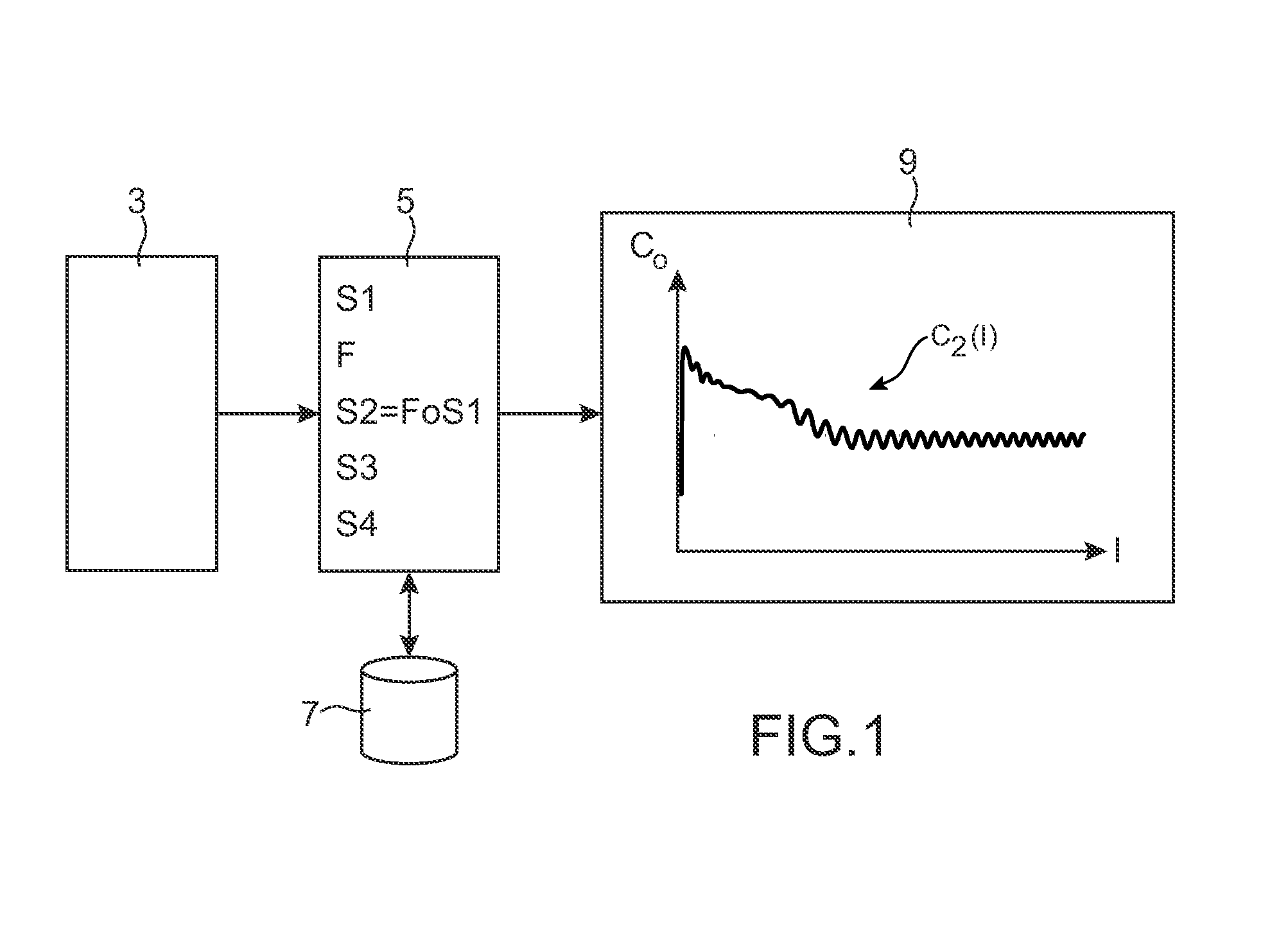
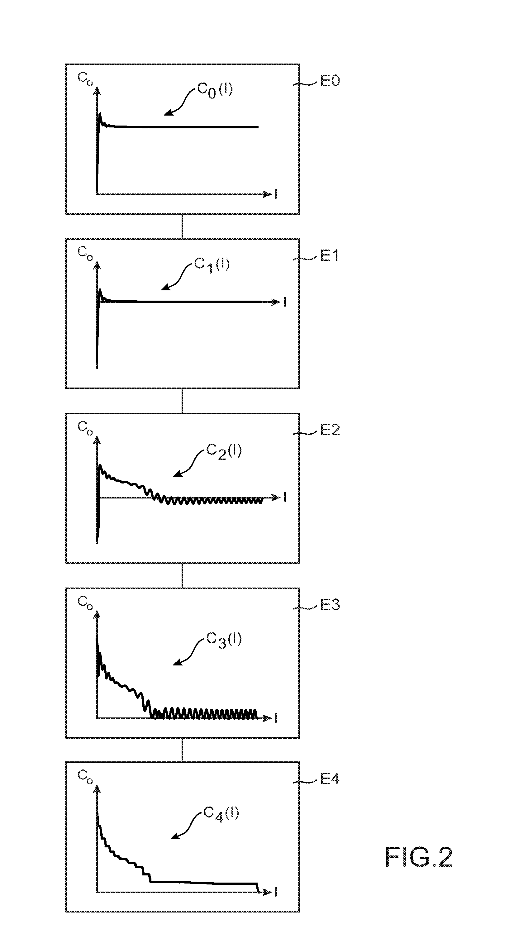
[0087]FIG. 2 shows the various steps in a simulation method according to the invention.

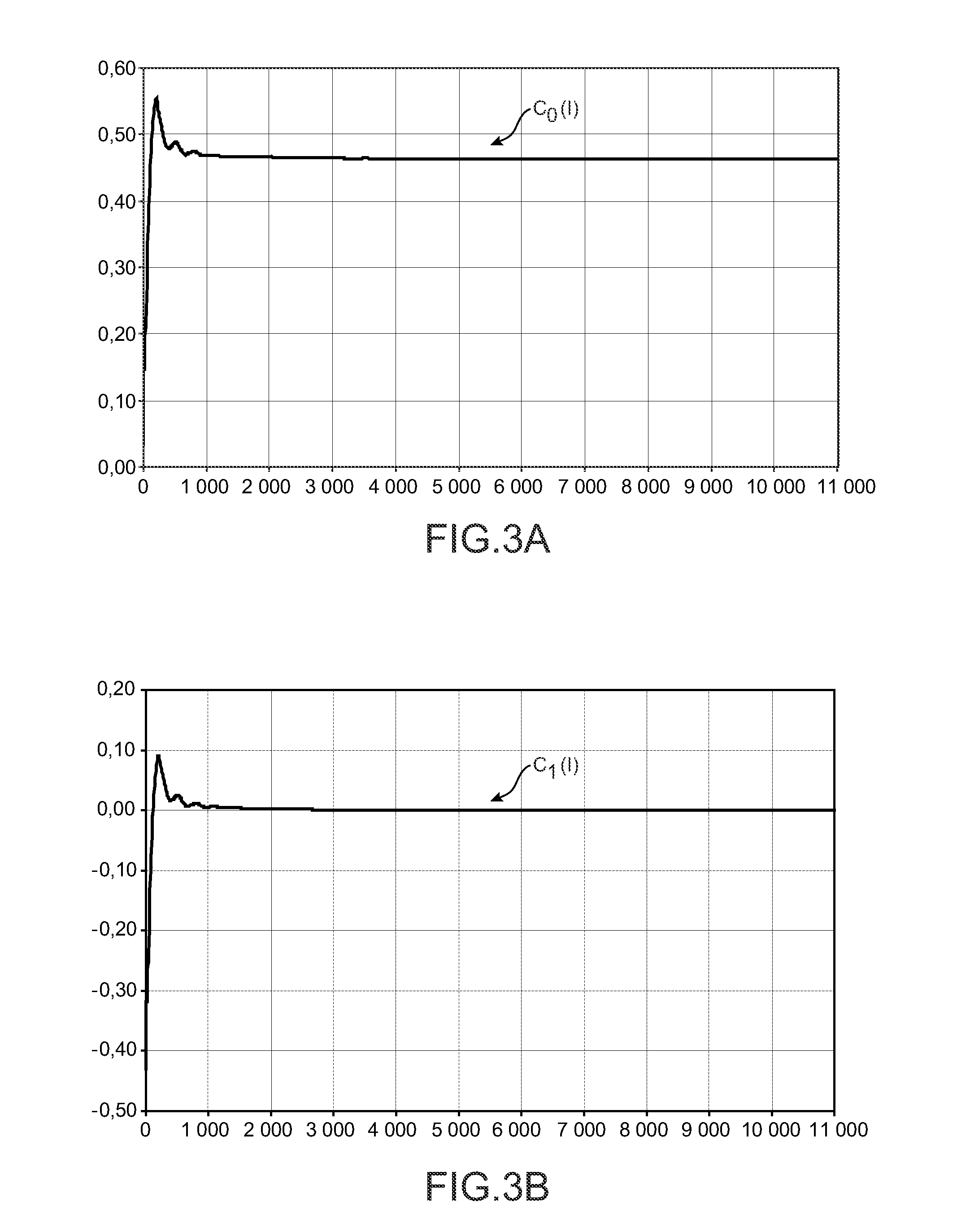
[0088]According to this example, a first finite series of values of the coefficient is available in the form of a table giving the value of the aerodynamic coefficient for each number of iterations, this number varying between 1 and a total number of iterations for example equal to 11 000. In the remainder of this document, the aerodynamic coefficient will be denoted C0, the current number of iterations will be denoted I and the total number of iterations will be denoted Imax.

[0089]FIGS. 3A to 3E show plots for the different steps of the method in FIG. 2.

[0090]Step E0 consists of plotting a preliminary variation curve C0(I) representative of the first series S1 of values of the aerodynamic coefficient as a function of the number of iterations I, as shown in the example in FIG. 3A.

[0091]The abscissa of the plot of the curve C0(I) is the number of iterations I and its ordinate is the aerodynamic coe...

second embodiment

[0141]FIG. 4 shows the different steps in a simulation method according to the invention.

[0142]As above, there is a first finite series S1 of values of the aerodynamic coefficient C0 in step E20 in the form of a table containing the value of the coefficient for a number of iterations I varying between 1 and a total number of iterations Imax.

[0143]Thus, there is also the plot of the preliminary variation curve C0(I) representative of the first series of values of the aerodynamic coefficient as a function of the number of iterations, as shown in FIG. 3A.

[0144]This second embodiment is different from the first, particularly in that the translation of the curve C0(I) is implicitly integrated into the locally expanding transformation.

[0145]Step E22 consists of applying a mixed linear-logarithmic transformation onto function C0(I).

[0146]To achieve this, the processing means 5 start by calculating a final value C0final=C0(Imax), a maximum value C0max=max(C0(I)), and a minimum value C0min=m...


PUM


Abstract

A computer method of simulating a fluid flow in an aircraft environment to determine at least one aerodynamic coefficient, comprising obtaining a first series of values of the aerodynamic coefficient. The method also includes defining a criterion for convergence of said aerodynamic coefficient, selecting a determined set of terms belonging to said first series, defining a monotonic function configured to make a relatively expanding transformation in said determined set relative to the complement of said set, applying said monotonic function on said first series to form a second series of values of the aerodynamic coefficient, determining said aerodynamic coefficient by plotting a variation curve representative of said second series of values of the aerodynamic coefficient, and displaying said variation curve including an intrinsic zoom of the convergence zone of said aerodynamic coefficient.

Description

CROSS-REFERENCES TO RELATED APPLICATIONS[0001]This application claims the benefit of the French patent application No. 10 59047 filed on Nov. 3, 2010, the entire disclosures of which are incorporated herein by way of reference.BACKGROUND OF THE INVENTION[0002]This invention relates to the general domain of aerodynamics and concerns digital simulation of aerodynamic flows for an aircraft.[0003]Its application lies in the aeronautic field for which the design of an aircraft requires precise knowledge of aerodynamic coefficients associated with its various elements.[0004]When designing an aircraft, an attempt is made to determine global aerodynamic coefficients associated with its various elements, for example coefficients associated with the wings such as lift, drag and the pitching moment.[0005]These coefficients can be determined in different ways, particularly by digital simulation of fluid flows that consists of analysing movements of a fluid or the effects of these movements by d...

Claims


Application Information

Patent Timeline
IPC IPC(8): G06F17/50
CPCG06F17/5009G06F2111/10G06F30/15Y02T90/00G01M9/08G06F30/28G05D1/0808G06F30/20
Inventor CALMELS, BENOIT
Owner AIRBUS OPERATIONS (SAS)
Why Eureka
Try Eureka