Reductant aqueous solution mixing device and exhaust aftertreatment device provided with the same

a technology of aqueous solution and a mixing device, which is applied in the direction of machines/engines, mechanical equipment, separation processes, etc., can solve the problems of urea aqueous solution pipe extending from the injector affecting the wall face of the engine room, and achieve compact space, large flow path cross section, and sufficient resistance to flow path.

Active Publication Date: 2014-07-17
KOMATSU LTD
View PDF0 Cites 13 Cited by
  • Summary
  • Abstract
  • Description
  • Claims
  • Application Information

AI Technical Summary

Benefits of technology

[0021]According to the first and ninth aspects of the invention, since the first bulging portion is provided to the elbow pipe, even when the injector attachment is offset toward the outlet of the elbow pipe, the flow path cross sectional area in the elbow pipe is not significantly narrowed and the exhaust gas flow is not inhibited. Further, the offset arrangement of the injector attachment keeps the injector and an elbow pipe for a reductant connected to the injector from protruding outward, thereby easily avoiding an interference with the other components. Further, since the first bulging portion bulges in a direction opposite to the injector attachment, it is less likely that the first bulging portion interferes with the other components.
[0028]According to the tenth aspect of the invention, since the filter device, the reductant aqueous solution mixing device and the selective catalytic reduction device are juxtaposed with each other, the flow direction of the exhaust gas in the respective devices can be aligned, so that the size of the entirety of the exhaust aftertreatment device can be further reduced.

Problems solved by technology

In the above, when the exhaust aftertreatment device is to be disposed in a limited space (e.g. an engine room) as in a construction machine, the urea aqueous solution pipe extending from the injector interferes with a wall face of the engine room.

Method used


Image

  • Reductant aqueous solution mixing device and exhaust aftertreatment device provided with the same
  • Reductant aqueous solution mixing device and exhaust aftertreatment device provided with the same
  • Reductant aqueous solution mixing device and exhaust aftertreatment device provided with the same

Examples


Embodiment Construction

)

[0037]Exemplary embodiment(s) of the invention will be described below with reference to the attached drawings.

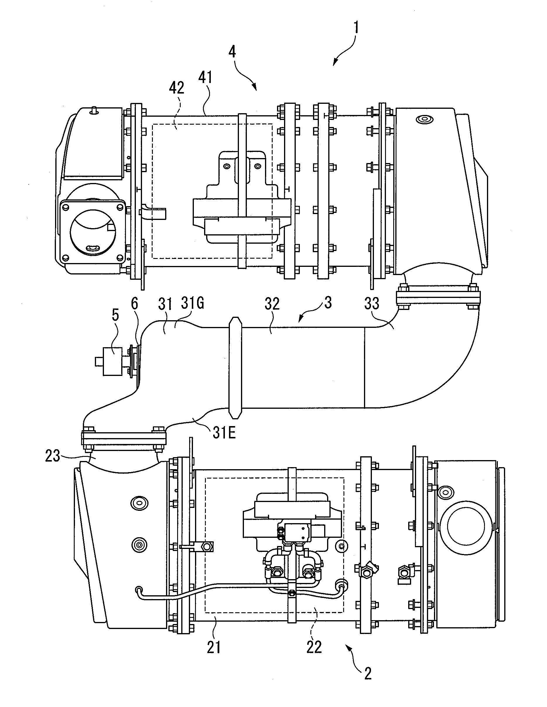
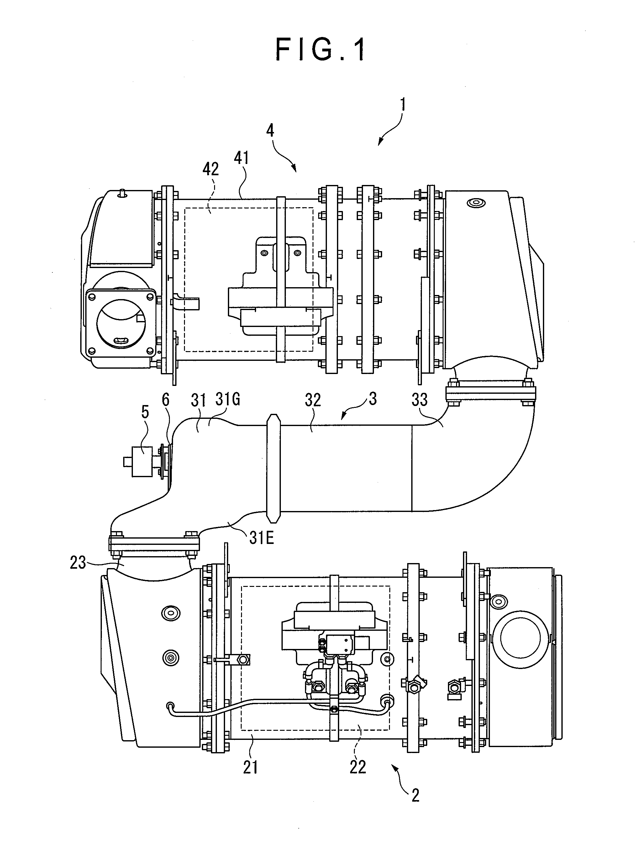
[0038]As shown in FIG. 1, the exhaust aftertreatment device 1 includes a filter device in a form of a diesel particulate filter (abbreviated as “DPF” hereinafter) device 2, a reductant aqueous solution mixing device (referred to as a mixing device hereinafter) 3, and a selective catalytic reduction (abbreviated as “SCR” hereinafter) device 4. These devices 2 to 4 are provided in the exhaust pipe in which the exhaust gas from a diesel engine (not shown) flows. In a construction machine such as a hydraulic excavator, wheel loader and bulldozer, the exhaust aftertreatment device 1 is housed in an engine room together with the engine.

[0039]The DPF device 2 includes a cylindrical casing 21 and a cylindrical DPF 22 housed inside the casing 21. The DPF 22 captures the particulate matters in the exhaust gas passing through the DPF 22. An oxidation catalyst may be provided upstream...


PUM


Abstract

A mixing device of an exhaust aftertreatment device includes: an elbow pipe attached to an outlet pipe of a filter device; a straight pipe connected to a downstream side of the elbow pipe to extend in a direction intersecting an axial line of the outlet pipe; and an injector attached to the elbow pipe, the injector injecting a reductant aqueous solution into inside the elbow pipe toward the straight pipe. The elbow pipe includes: an inlet connected with the outlet pipe; an outlet connected with the straight pipe; a direction-changing section provided between the inlet and the outlet; and an injector attachment provided outside the direction-changing section and attached with the injector. The injector attachment is offset toward the outlet. The direction-changing section includes a first bulging portion provided by bulging outward a portion thereof opposite to the injector attachment.

Description

TECHNICAL FIELD[0001]The invention relates to a reductant aqueous solution mixing device and an exhaust aftertreatment device provided with the reductant aqueous solution mixing device. Specifically, the invention relates to a reductant aqueous solution mixing device used for supplying a reductant aqueous solution such as urea aqueous solution to a selective catalytic reduction to purify exhaust gas and an exhaust aftertreatment device provided with the reductant aqueous solution mixing device.BACKGROUND ART[0002]An exhaust aftertreatment device that purifies nitrogen oxides (NOx) contained in exhaust gas of an engine with a selective catalytic reduction (abbreviated as “SCR” hereinafter) has been known. Urea aqueous solution injected by an injector is supplied to the SCR. The injector is attached as a component of a mixing device provided upstream of the SCR (see, for instance, Patent Literatures 1 and 2). The urea aqueous solution is injected from the injector to exhaust gas flowi...

Claims


Application Information

Patent Timeline
Patent Type & Authority Applications(United States)
IPC IPC(8): F01N3/035
CPCF01N3/035F01N3/208F01N2240/20F01N2470/04F01N2470/10F01N2610/02F01N2610/1453Y02T10/12F01N3/20F01N3/28B01D53/94
Inventor WATAHIKI, TATSUYAKOBAYASHI, HIDEHIKOCHINO, HIROYUKI
Owner KOMATSU LTD
Why Eureka
Try Eureka