Heat pump apparatus and method of controlling heat pump apparatus

a heat pump and heat pump technology, applied in the direction of lighting and heating apparatus, heating types, refrigeration components, etc., can solve the problem of all these refrigerants being flammabl

Inactive Publication Date: 2014-07-17
MITSUBISHI ELECTRIC CORP
View PDF17 Cites 28 Cited by
  • Summary
  • Abstract
  • Description
  • Claims
  • Application Information

AI Technical Summary

Benefits of technology

[0011]The heat pump apparatus according to the present invention closes the first valve and the second valve when the refrigerant leaks from the first refrigerant circuit, serving as a primary circuit, into the fluid circuit, serving as a secondary circuit, thus preventing the refrigerant circu...

Problems solved by technology

Disadvantageously, all of these refrigerants are flammable, unlike ...

Method used


Image

  • Heat pump apparatus and method of controlling heat pump apparatus
  • Heat pump apparatus and method of controlling heat pump apparatus
  • Heat pump apparatus and method of controlling heat pump apparatus

Examples


embodiment 1

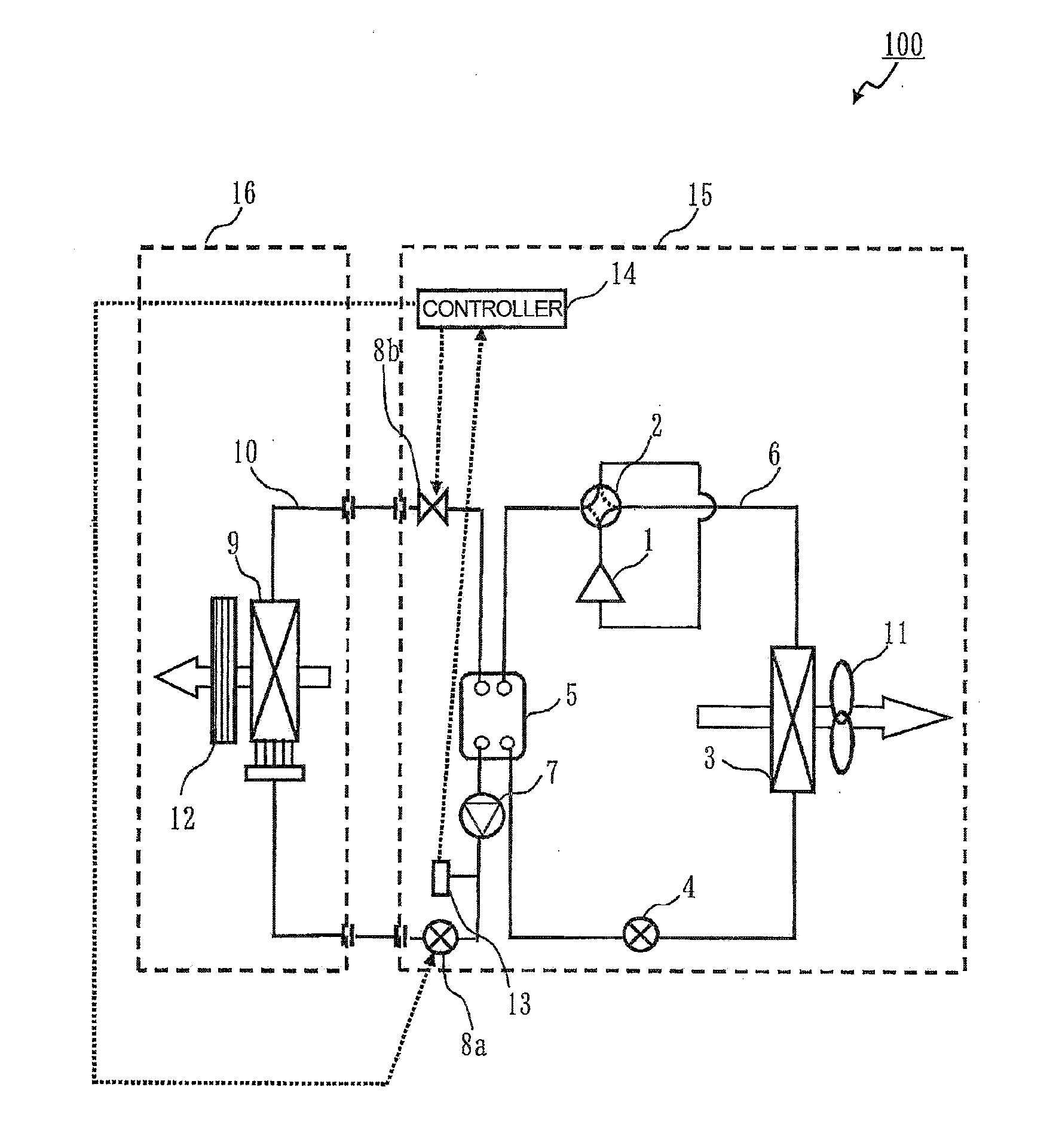
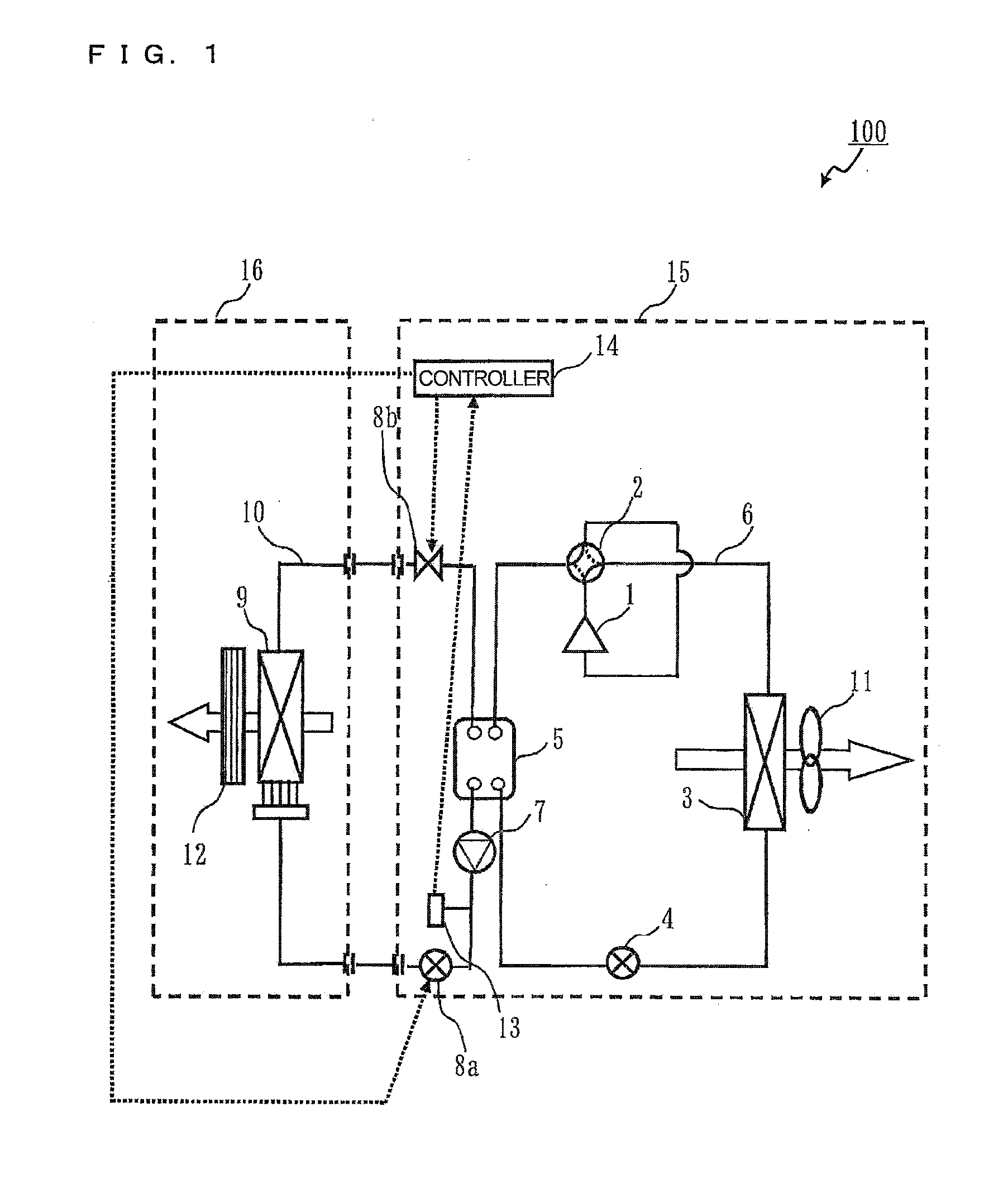
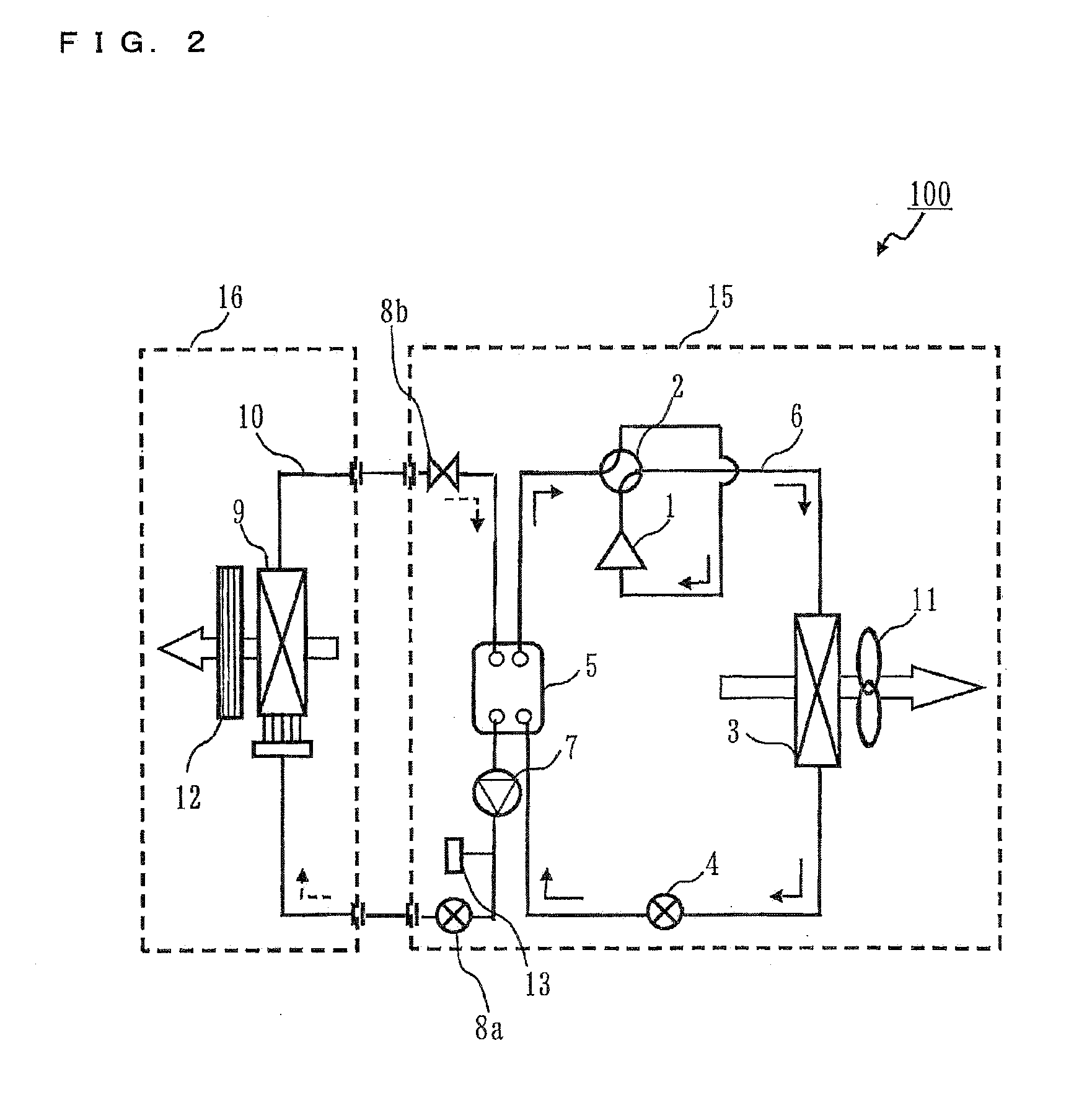
[0023]FIG. 1 is a diagram illustrating the configuration of an air-conditioning apparatus 100 according to Embodiment 1. In FIG. 1, each blanked arrow indicates the flow of air and each dotted arrow indicates the flow of a signal.

[0024]The air-conditioning apparatus 100 includes a refrigerant circuit 6 (first refrigerant circuit or primary circuit) that includes a compressor 1 (first compressor), a four-way valve 2, a heat exchanger 3 (first heat exchanger), an expansion valve 4 (first expansion mechanism), an intermediate heat exchanger 5 (first intermediate heat exchanger) sequentially connected in loop by pipes. The air-conditioning apparatus 100 further includes a water circuit 10 (fluid circuit or secondary circuit) that includes the intermediate heat exchanger 5, a pump 7, a valve 8a (first valve), a heat exchanger 9 (load heat exchanger), and a valve 8b (second valve) sequentially connected in loop by pipes. A flammable refrigerant, such as a propane or isobutane, having a lo...

embodiment 2

[0057]Embodiment 2 will be described with respect to an air-conditioning apparatus 100 including a plurality of primary circuits. Although the air-conditioning apparatus 100 including two primary circuits will be described below as an example, the air-conditioning apparatus 100 may include three or more primary circuits.

[0058]In the air-conditioning apparatus 100 according to Embodiment 2, the same components as those in the air-conditioning apparatus 100 according to Embodiment 1 are designated by the same reference numerals.

[0059]FIG. 5 is a diagram illustrating the configuration of the air-conditioning apparatus 100 according to Embodiment 2. In FIG. 1, each blanked arrow indicates the flow of air and each dotted arrow indicates the flow of a signal.

[0060]The air-conditioning apparatus 100 includes a refrigerant circuit 6a (first refrigerant circuit or primary circuit) including a compressor 1a (first compressor), a four-way valve 2a, a heat exchanger 3a (first heat exchanger), a...

embodiment 3

[0093]Embodiment 3 will be described with respect to placement of the intermediate heat exchanger 5 (5a, 5b) in Embodiments 1 and 2. The placement will be described with respect to the air-conditioning apparatus 100 according to Embodiment 2 as an example.

[0094]FIG. 8 is an exploded perspective view of a typical plate heat exchanger.

[0095]FIGS. 9 to 11 are diagrams illustrating arrangement of the intermediate heat exchangers 5a and 5b according to Embodiment 3. In FIGS. 9 to 11, solid line arrows indicate the flow of refrigerant during the cooling operation and broken line arrows indicate the flow of water. During the heating operation, the refrigerant flows in a direction opposite to that indicated by the solid line arrows. In FIGS. 9 to 11, an up-down direction corresponds to a vertical direction.

[0096]In FIGS. 9 to 11, it is assumed that each of the intermediate heat exchangers 5a and 5b is a plate heat exchanger. As illustrated in FIG. 8, the plate heat exchanger includes a plur...


PUM


Abstract

In a heat pump apparatus of an indirect type including a primary circuit on a heat source side and a secondary circuit on a load side, a refrigerant in the primary circuit is prevented from leaking through the secondary circuit.
An air-conditioning apparatus includes a leakage detecting device that detects leakage of the refrigerant circulated through a refrigerant circuit, serving as the primary circuit, from an intermediate heat exchanger into a water circuit, serving as the secondary circuit, and a controller that closes valves arranged on both sides of the intermediate heat exchanger in the water circuit to prevent water containing the refrigerant from flowing beyond the valves when the leakage detecting device detects the leakage.

Description

TECHNICAL FIELD[0001]The present invention relates to a technique for securing safety when a refrigerant leaks from a heat pump apparatus.BACKGROUND ART[0002]An air-conditioning apparatus (an example of a heat pump apparatus) has been known which utilizes a refrigeration cycle technique using a refrigerant as a way of cooling, heating, or dehumidifying a room.[0003]Fluorine compounds, such as R410A that is hydrofluorocarbon (HFC), are widely used as refrigerants in air-conditioning apparatuses. These refrigerants, however, have a considerable impact on global warming. In terms of prevention of global warming, therefore, it is desirable to use refrigerants having a less impact on global warming. Accordingly, the use of refrigerants having a less impact on global warming, such as R32 that is HFC, R1234yf that is hydrofluoro-olefin (HFO), propane and isobutene that are hydrocarbons, has been proposed. Disadvantageously, all of these refrigerants are flammable, unlike the conventional r...

Claims


Application Information

Patent Timeline
IPC IPC(8): F25B49/00F25B25/00
CPCF25B25/005F25B49/005F25B49/02F24F1/26F25B13/00F25B39/00F25B2313/003F25B2400/06F25B2400/12F25B2500/18F25B2500/222F24F11/70F24F11/36
Inventor OKAZAKI, TAKASHI
Owner MITSUBISHI ELECTRIC CORP
Why Eureka
Try Eureka