
Fluid Leak Detection and Shutdown Apparatus

a technology of fluid leak detection and shutdown apparatus, which is applied in the direction of fluid tightness measurement, valve operating means/release devices, instruments, etc., can solve the problems of less realistic automatic leak detention apparatus, more likely to be detected, and significant damage to the machine and/or surrounding structur

Inactive Publication Date: 2014-07-17
GUY KEVIN DUANE +1
View PDF31 Cites 21 Cited by
  • Summary
  • Abstract
  • Description
  • Claims
  • Application Information

AI Technical Summary

Benefits of technology

The fluid leak detection and shutdown apparatus includes a flow sensor and a solenoid shutoff valve. The flow sensor is connected to a secondary fluid flow line and detects minimal flow rates. The solenoid shutoff valve is activated based on the flow sensor output. The technical effect of this apparatus is the ability to detect and shut off fluid leaks quickly, which can prevent damage and reduce downtime.

Problems solved by technology

However, as a practical matter, having an automated leak detention apparatus everywhere a leak may occur is not realistic due to the multitude of potential leak locations causing undue complication and cost.
Wherein normally without the presence of any type of leak detection apparatus, a small liquid leakage from a machine, say for instance hidden underneath a large heavy ice making machine (that is rarely moved) that has a low volumetric flow rate leak or in other words a seeping leak can cause significant damage to the machine and / or surrounding adjacent structure prior to being detected.
Unfortunately, the ice machine will continue to work perfectly during its small leakage phase thus not alerting a user to the presence of the slight leakage condition, at least until the surrounding structure suffers significant damage, wherein the leak would more likely be detected.
Thus, this situation can continue for quite some time until extensive damage has occurred in the hidden machine portions and / or support structure, wherein at some later in time point the structural damage eventually becomes obvious, wherein the structural damage from the liquid seepage is more excessive than it should be.
Thus, the result is that the support structure suffers additional damage that is hidden from view in addition to the leaked fluid, typically water or even worse a fluid that is toxic or chemical in nature that could risk further safety, electrical risk, or environmental harm.
Unfortunately, water damage can most likely occur one the office or home is vacant wherein a frozen pipe can be burst shutoff valves can fail to say toilet tanks or for instance refrigerator ice makers can have line ruptures in addition to dishwashers, and items such as broken hoses to washing machines.
The typical damage would include damage to wallboard, wallpaper, paint, electrical fixtures and wiring, carpeting and padding, vinyl flooring, subflooring, or building structure, plus furniture and other household items.
In addition, items such as financial records, photos, and other irreplaceable items can be destroyed beyond retrieval or repair.
Further, later forming issues can include hazardous molds and the like that will require even more costly and difficult cleanups.
Thus, the key issues for the leak detection apparatus involve, small space or size requirements for the apparatus, as the specific placement location for the apparatus may be in a confined area with difficult accessibility, a further issue in the leak detection apparatus is the sensitivity of generating a perceptible output from a very low liquid leakage flow rate, usually in the range of about one-third (⅓) of a gallon per minute to detect a leak prior to a significant damage occurring, i.e. catching the leak as soon as possible.
Another issue for the leak detection apparatus is to ideally have a single leak detection apparatus able to cover a multitude of potential leak points for ease of installation and to reduce cost, and in addition for the leak detection apparatus to automatically shutdown the root source of the leakage based upon the detection of leakage to minimize damage either to machines, equipment, or the surrounding structure or environment from leakage damage.
Also in Wilson, because the system requires electricity to operate, a general power failure will automatically shut off of the water supply.
Wilson does not also teach the automated shutting off of the water supply in the event of a leak occurring when there is no one around the house or water system, as Wilson requires the manual selectively shutting off of the water system, suggesting that the water system be completely shut off when the homeowner is absent, however, in this case the homeowner could just manually shut off their main water valve without the Wilson system.
Davis does not teach any form of leak detection or water system automatic shut off in the event of a water system leak, as there is no measure of flow rate with a flow meter.
In Cooper, the pressure detector works via detecting pressure degradation and / or flow rate increase, however, pressure detection to monitor low leakage situations would be problematic, as with slow leaks, pressure drop may not even occur as the municipal water supply will maintain a constant feed pressure of water into the system unless the flow rate is excessively high causing a water system pressure drop, the only instance wherein system pressure drops would detect small leakage is when the system does not have a pressure water or liquid feed, such as a closed off system, however, the teaching is for a municipal constant water pressure feed system, see column 6, lines 10-15, thus water pressure sensing would only detect relatively high flow rates.
In operation in Cooper, the flow detector is used for sensing user demand, in which case there is user demand, then the main valve remains open until user demand ceases, at which time flow rate detection and pressure drop detection would activate closing of the main valve, although teaching of how user demand is really sensed is not present-however, it would typically involve some form of electronic sensor at each water use appliance, which would be complicated and costly, Cooper does mention using the timer for a time window in which user demand is assumed thus negating when flow or pressure sensing would activate closing the main valve, however, this could facilitate a leak being allowed to proceed (i.e. no main valve shut off) if the user demand time window is longer.
Note that there is no need for a flow meter in Maresca Jr., which would be considered undesirable due to the low leakage flow rates required to be detected being around 0.1 gallon per hour.

Method used


Image

  • Fluid Leak Detection and Shutdown Apparatus
  • Fluid Leak Detection and Shutdown Apparatus
  • Fluid Leak Detection and Shutdown Apparatus

Examples


Embodiment Construction

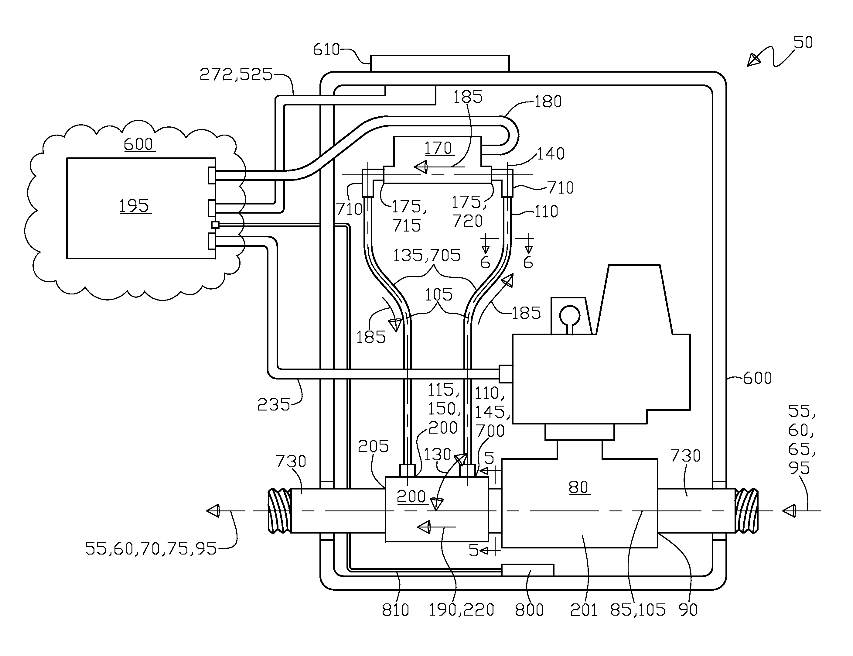
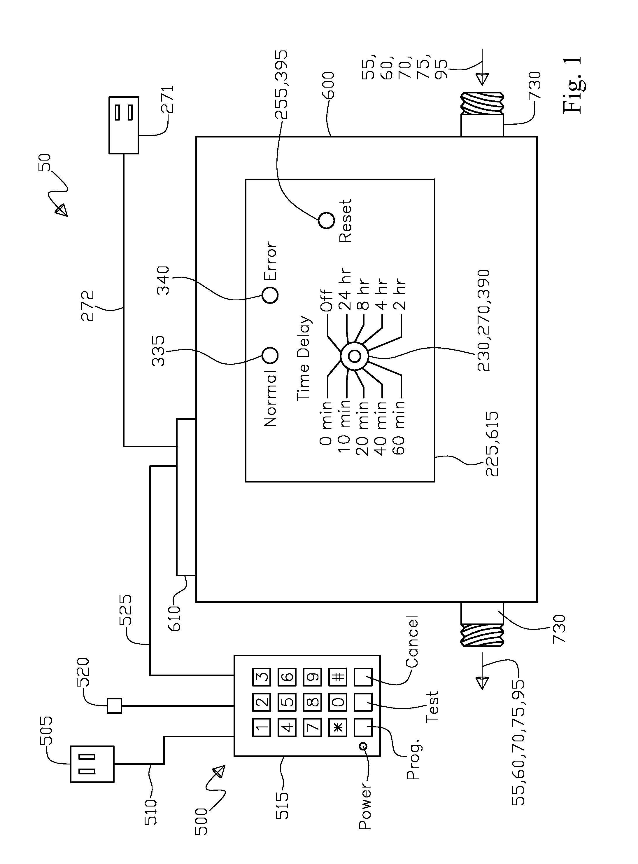
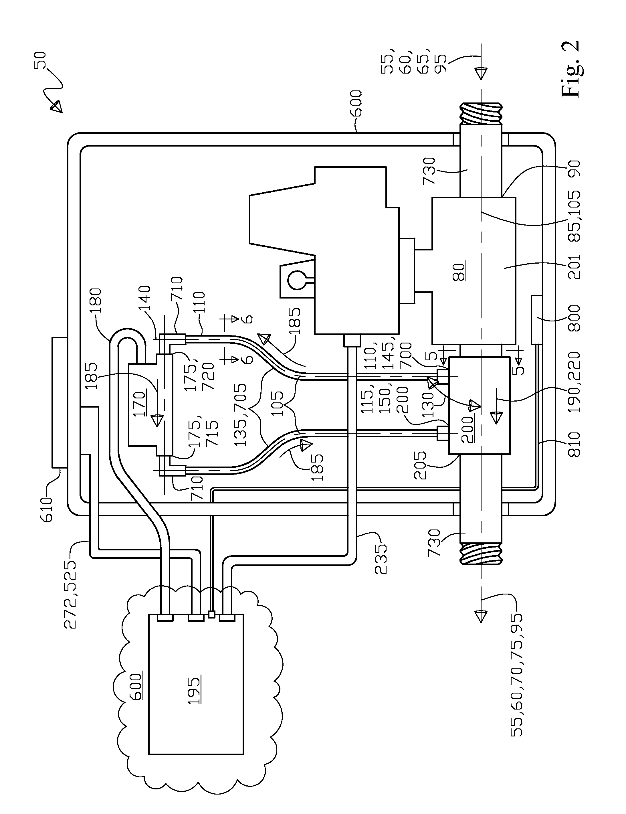
[0151]With initial reference to FIG. 1 shown is a side elevation view of the fluid leak detection and shutdown apparatus 50 that includes an enclosure 600, the nipple connections 730 for flow in 65 and flow out 70, wherein the nipple connections 730 are connected to the fluid distribution system 55 for the total fluid distribution system flow rate 60. Further FIG. 1 shows the inlet 65 of the apparatus 50, the outlet 70 of the apparatus 50, the fluid flow direction 95, the article 75 of the fluid distribution system 55 that consumes a portion 75 of the total fluid distribution system flow rate 60. Also, FIG. 1 shows a remote indicator panel 615, that includes a time delay selector switch 390, a normal green indicator light 335, an error red indicator light 340, and a reset switch 395. In addition, FIG. 1 shows an initial electrical power supply 271 and electrical power supply communication link 272 that is connected to a 10 position terminal block 610, further shown is the modem modu...


PUM


Abstract

An apparatus and method for a fluid leak detection and shutdown for a fluid distribution system having a total system flow rate. The apparatus includes a solenoid shutoff valve having a normally open state and an activated closed state with a flow capacity matched to the total fluid distribution system flow rate. The apparatus also has a primary fluid flow line and a smaller capacity secondary fluid flow line. The apparatus includes a flow sensor in fluid communication with the secondary fluid flow line, wherein the flow sensor has a perceptible output and a flow rate capacity less than the solenoid shutoff flow capacity. Operationally, the flow sensor receives a portion of the solenoid shutoff valve flow capacity in priority over the primary fluid flow line, allowing the flow sensor to detect minimal flow rates and using the perceptible output to activate the solenoid shutoff valve into the closed state.

Description

RELATED APPLICATIONS[0001]This is a continuation in part (CIP) patent application of U.S. patent application Ser. No. 13 / 272,219 filed on Oct. 13, 2011 by Kevin Duane Guy of Yuma, Colorado, US.TECHNICAL FIELD[0002]The present invention relates generally to a fluid leak detection and shutdown apparatus. More specifically, the present invention relates to an electro-mechanical based liquid leak detection and shutdown apparatus for detecting the presence of a selected amount of liquid flow in a particular location in a liquid line, for the purpose of initiating a sequence of actions that is intended to shutdown the upstream liquid flow of liquid to prevent further damage to an environment that would be susceptible to damage from the unintended liquid flow.BACKGROUND OF INVENTION[0003]Typically the ideal location for first detecting a leak is adjacent to the source of the leak for the purpose of not only stopping the leaks as soon as possible to minimize damage, but to pinpoint the actu...

Claims


Application Information

Patent Timeline
Patent Type & Authority Applications(United States)
IPC IPC(8): F16K17/36
CPCF16K17/36E03B7/071F17D5/02G01M3/2807Y02A20/15Y10T137/7759
Inventor GUY, KEVIN DUANEELM, JOHN
Owner GUY KEVIN DUANE
Learn More