Tool holder and tool arrangement

Inactive Publication Date: 2014-07-17
OTTO BILZ WERKZEUGFAB
View PDF9 Cites 7 Cited by
  • Summary
  • Abstract
  • Description
  • Claims
  • Application Information

AI Technical Summary

Benefits of technology

[0010]It is another object of the present invention to disclose a tool holder that allows for a change between several operating fluid supply configurations in a manner which is as little prone to error as possible or is, preferably, error-free.
[0011]It is

Problems solved by technology

Conventionally, however, not all the fluid paths provided in the tool holder are needed.
If a tool holder of this kind, in which at least some of the fluid paths are closed off manually, is to be used in a production machine comprising a different configuration (as regards the supply lines for the operating fluid), complex manual interventions are unavoidable.
Manual modification of this kind is in principle prone to error.
In particular, with an inexperienced worke

Method used


Image

  • Tool holder and tool arrangement
  • Tool holder and tool arrangement
  • Tool holder and tool arrangement

Examples


Embodiment Construction

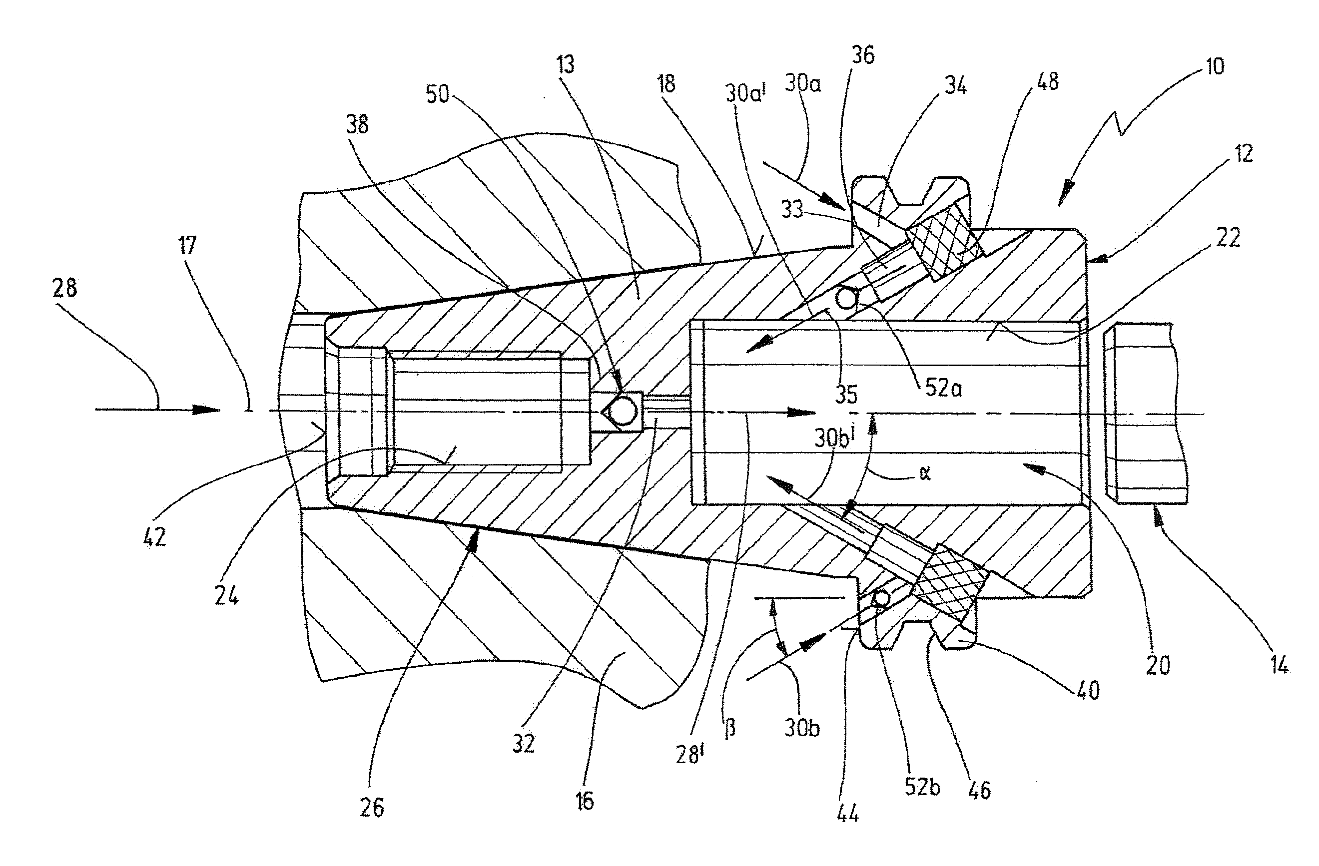
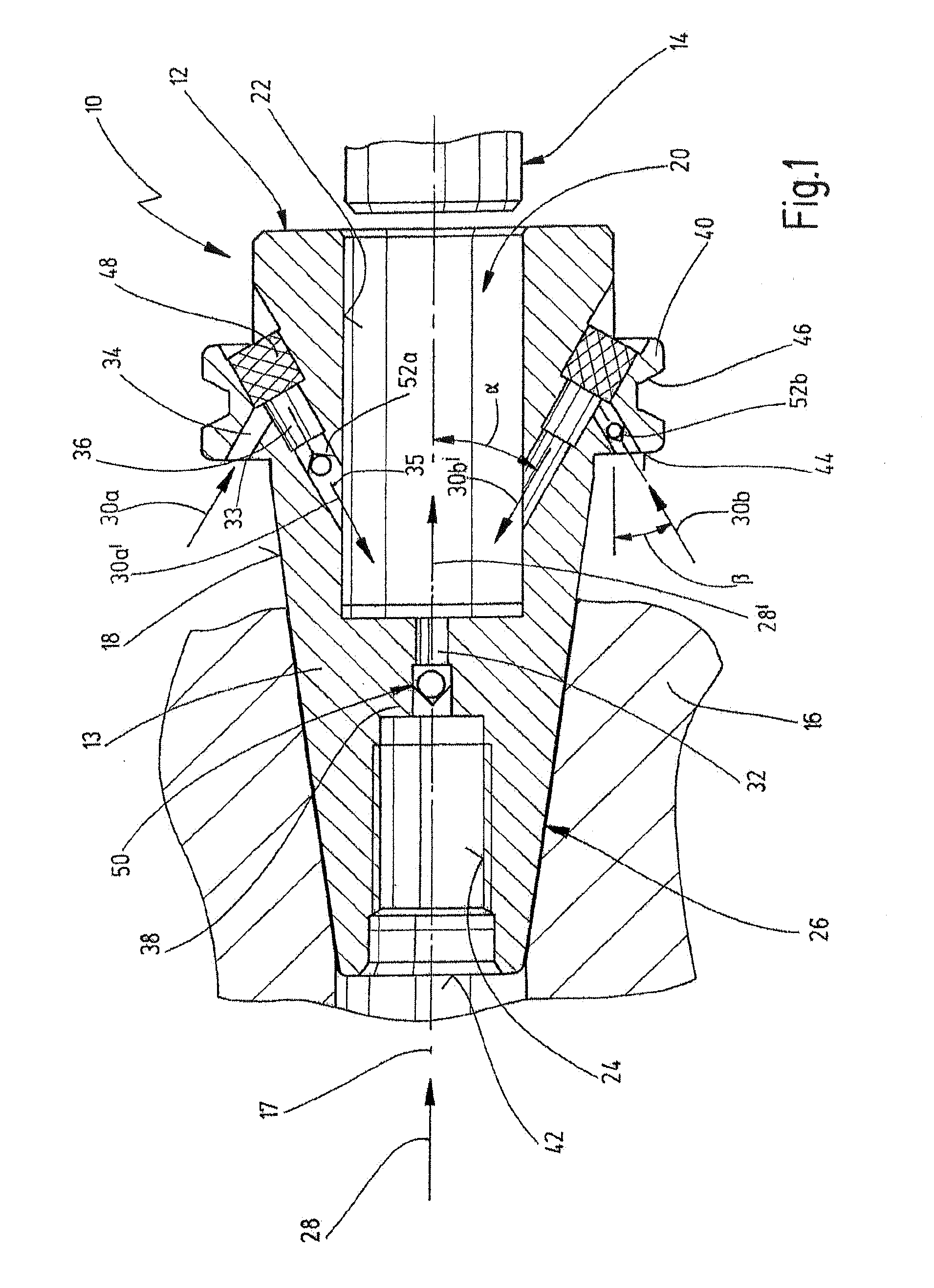
[0042]FIG. 1 shows a cutaway partial lateral illustration of a tool arrangement that is indicated generally by reference numeral 10.

[0043]The tool arrangement 10 has a tool holder 12, which may be constructed to receive a machining tool 14. FIG. 1 merely indicates, for reasons of clarity, a shank of the machining tool 14 in a cutaway partial illustration. The machining tool 14 may be for example a tool for stock removal. It will be appreciated that other types of machining tools 14 may also be used. Tools of the stock removal type may for example include drilling tools, milling tools, lathing tools or similar.

[0044]The tool holder 12 is further configured to be coupled to a drive spindle 16, which is shown in FIG. 1, again for reasons of clarity only in a simplified form in a cutaway partial illustration. The drive spindle 16 may be configured to drive the tool holder 12, together with the machining tool 14 which may be received therein, about a longitudinal axis 17, in particular t...


PUM


Abstract

The present invention relates to a tool holder, in particular a steep-taper shank type tool holder, the tool holder comprising at least one mounting surface, in particular a mounting cone, for being received and driven by a drive spindle, and further comprising at least one integrated fluid path for an operating fluid, wherein at least one flow blocking member is associated with the at least one fluid path and is configured to block or release the at least one fluid path in a manner depending on flow direction. The at least one flow blocking member may be configured and arranged such that it permits flow for the operating fluid in the intended direction of supply and does not permit flow for the operating fluid in opposition to the intended direction of supply. The tool holder may be arranged as a chuck or a clamping chuck, for example.

Description

CROSS-REFERENCES TO RELATED APPLICATIONS[0001]This application claims priority from German utility model application 20 2013 100 177.5, filed on Jan. 14, 2013. The entire content of this priority application is incorporated herein by reference.BACKGROUND OF THE INVENTION[0002]The present invention relates to a tool holder, in particular a steep-taper shank, comprising at least one mounting surface, in particular a mounting cone, for being received and driven by a drive spindle, and comprising at least one integrated fluid path for an operating fluid. Further, the invention relates to a tool arrangement comprising a tool holder of this kind and a machining tool that is received on the tool holder.[0003]Tool holders of a general type are well known in the art. Tool holders may for example also be referred to as clamping chucks or, more generally, chucks. Tool holders are conventionally configured to receive a machining tool, for example a tool for stock removal, for example a drilling...

Claims


Application Information

Patent Timeline
IPC IPC(8): B23Q11/10B23B31/02B23Q3/12
CPCB23Q11/1023B23Q11/1069B23B31/02B23Q3/12B23B2250/12B23B2260/142Y10T279/17111
Inventor SCHNEIDER, WERNER
Owner OTTO BILZ WERKZEUGFAB
Why Eureka
Try Eureka