
Wireless charger with combined electric radiation shielding and capacitive sensing functions

a capacitive sensing function and charger technology, applied in the field of wireless chargers, can solve the problems of electromagnetic interference (emi), complex electronic circuitry, and device usage rang

Inactive Publication Date: 2014-07-17
LITE ON TECH CORP
View PDF4 Cites 50 Cited by
  • Summary
  • Abstract
  • Description
  • Claims
  • Application Information

AI Technical Summary

Benefits of technology

This patent is about a wireless charger that can detect when an electronic device is placed on it and quickly switch to a charging mode to start charging. The charger uses a special shielding system to reduce electric radiation and has a capacitive sensor to detect changes in capacitance between the charger and the environment. This allows the charger to send a signal to the device when it's ready to charge and switch to a charging mode. The charger then returns to a standby mode when the device is fully charged or if the charging is complete. Overall, this technology combines the functions of electric radiation shielding and capacitive sensing in a wireless charger to improve efficiency and safety.

Problems solved by technology

Nowadays, complex electronic circuitry is found in all sorts of devices used in the home or other places.
However the length of the wires could limit the usage range of the devices and the wires easily get entangled with other wire, causing inconvenience.
A major problem of the wireless charging is electromagnetic interference (EMI).
EMI is a common problem which occurs with electronic devices when the performance of a device is disturbed or interrupted by electromagnetic radiation or electromagnetic conduction.
Generally, to recognize that there is a chargeable device on the charging pad of the wireless charger, standard wireless charger is pinging all the time which leads to additional EMS (electromagnetic susceptibility) issues.

Method used


Image

  • Wireless charger with combined electric radiation shielding and capacitive sensing functions
  • Wireless charger with combined electric radiation shielding and capacitive sensing functions
  • Wireless charger with combined electric radiation shielding and capacitive sensing functions

Examples


Embodiment Construction

[0013]In the following detailed description, only certain exemplary embodiments of the present invention are shown and described, by way of illustration. As those skilled in the art would recognize, the described exemplary embodiments may be modified in various ways, all without departing from the spirit or scope of the present invention. Accordingly, the drawings and description are to be regarded as illustrative in nature, and not restrictive.

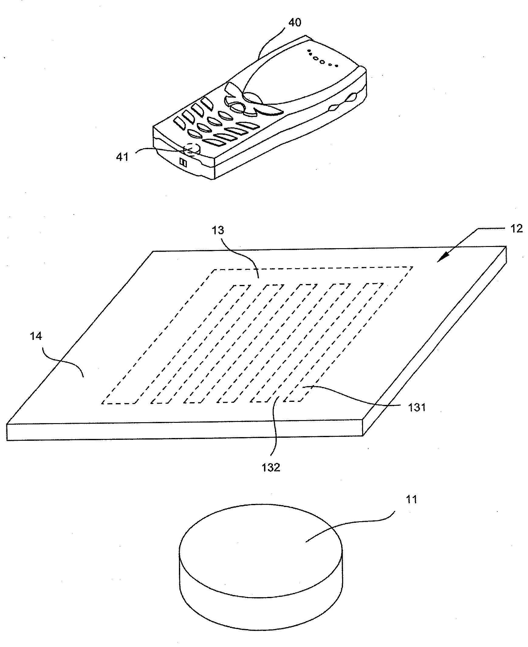
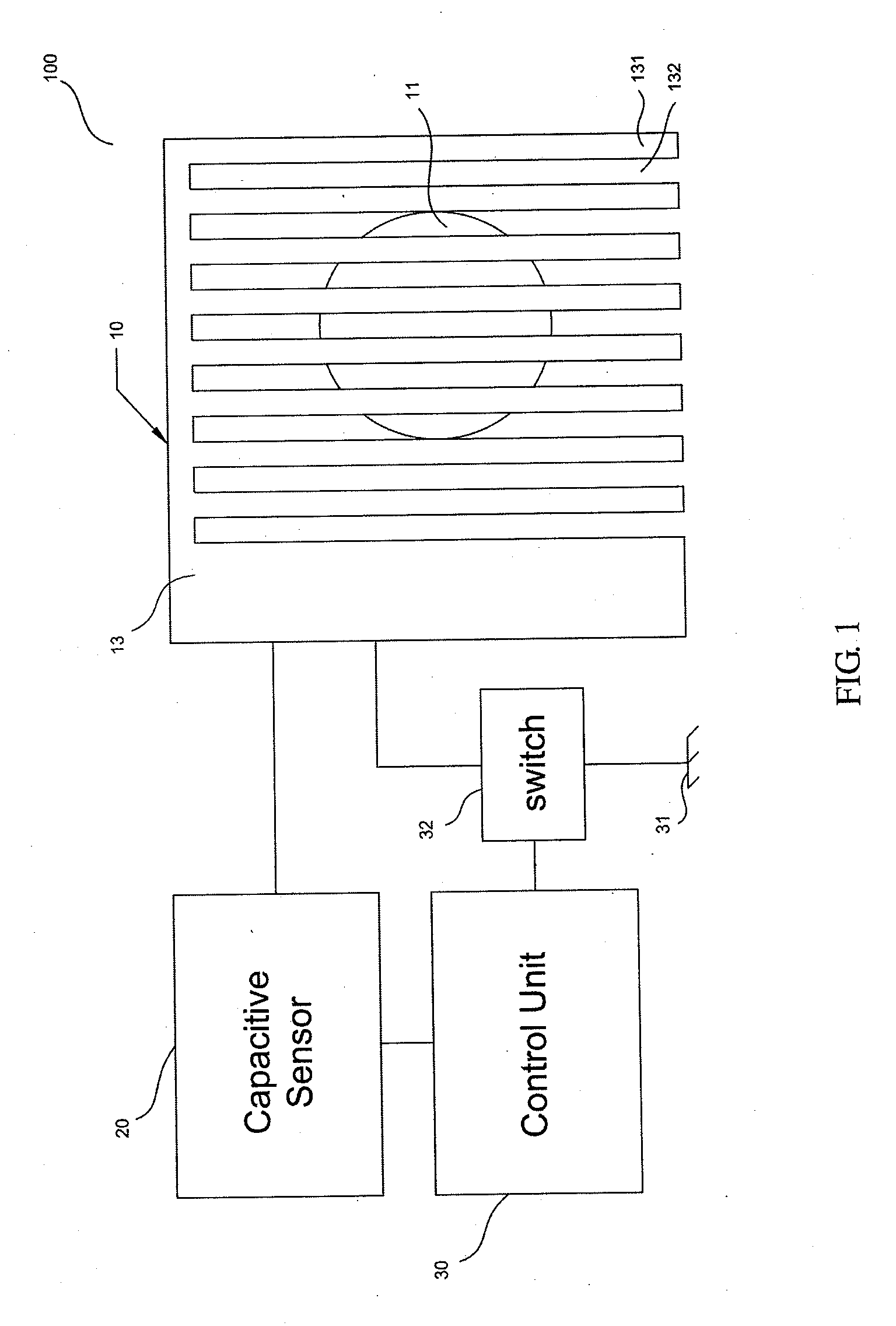
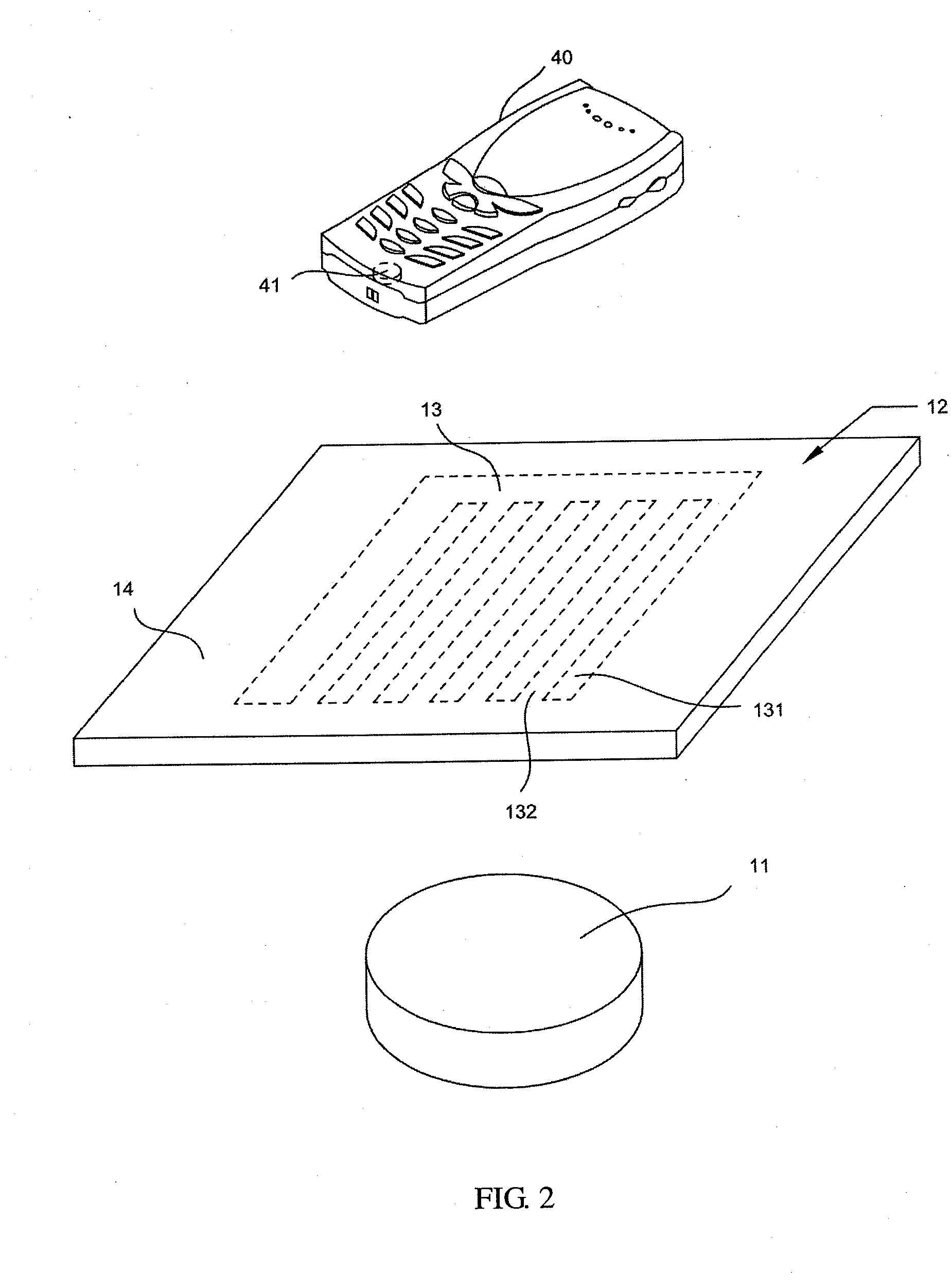
[0014]FIG. 1 is a schematic diagram showing an embodiment of the wireless charger 100 of the invention. FIG. 2 shows a pictorial drawing of the wireless charger of the invention with a portable electronic device. The wireless charger 100 is for charging an electronic device 40 wirelessly. In general, the electronic device 40 has a second coil 41 in it so as to take power from the electromagnetic field generated by the wireless charger 100 and convert it into electrical current to charge the battery in the electronic device 40. As shown in FIG...


PUM


Abstract

A wireless charger with combined electric radiation shielding and capacitive sensing functions is provided. The wireless charger comprises a charging module, a capacitive sensor, and a control unit. The charging module comprises a first coil, a placing area, and a comb-shaped shielding located between the placing area and the first coil. The capacitive sensor is connected to the comb-shaped shielding to detect the capacitance varient between the comb-shaped shielding and the environment. When the wireless charger is in a standby mode, the comb-shaped shielding is for sensing capacitance. When the capacitance varient exceeds a predefined threshold and an electronic device for wireless charging is placed on the placing area, the control unit switches the wireless charger to a charging mode and the comb-shaped shielding is for electric radiation shielding.

Description

BACKGROUND OF THE INVENTION[0001]1. Technical Field[0002]The present invention relates to a wireless charger. More particularly, the present invention relates to a wireless charger with combined electric radition shielding and capacitive sensing functions.[0003]2. Description of Related Art[0004]Nowadays, complex electronic circuitry is found in all sorts of devices used in the home or other places. Such devices are usually charged by a wired method or contain a battery to provide necessary electricity. However the length of the wires could limit the usage range of the devices and the wires easily get entangled with other wire, causing inconvenience. Therefore, inductive charging (also known as wireless charging) of electronic devices is increasingly popular. The inductive charging is fulfilled by electromagnetic induction. A major problem of the wireless charging is electromagnetic interference (EMI). EMI is a common problem which occurs with electronic devices when the performance...

Claims


Application Information

Patent Timeline
IPC IPC(8): H02J7/00H02J50/00H02J50/10H02J50/70H02J50/80H02J50/90
CPCH02J7/007H02J7/0044H02J9/005H04B15/04Y04S20/20Y02B70/30H02J50/90H02J50/70H02J50/10H01F38/14H02J50/005H02J50/12H02J50/80
Inventor GRAF, STEFANWALDSCHMIDT, ANDREROTH, KARSTENLINDENSTRUTH, LARS
Owner LITE ON TECH CORP
Learn More