Heat exchange type cooling apparatus for a transformer

a technology of heat exchange and cooling apparatus, which is applied in the direction of transformer/inductance details, transformer/inductance with temperature compensation, basic electric elements, etc., can solve the problems of transformer operation generating significant heat, increasing generation amount, voltage transformation efficiency, etc., and achieves the effect of saving energy, light weight and small siz

Inactive Publication Date: 2014-07-17
KIM GAP DONG
View PDF2 Cites 1 Cited by
  • Summary
  • Abstract
  • Description
  • Claims
  • Application Information

AI Technical Summary

Benefits of technology

[0011]An object of the present disclosure is to provide to a heat exchange type cooling system for a transformer capable of being fabricated at a light weight and a small size, saving an energy, and having a high durability to a noise or a vibration and a high efficiency cooling performance.

Problems solved by technology

As a capacity of a transformer increases, a heat generation amount increases and a temperature rise becomes large, such that a problem occurs in a voltage transformation efficiency.
The transformer in operation generates a significant heat.
However, in the case of a blowing fan scheme that has been mainly used conventionally, a blowing fan having a weight of several hundreds of kilograms is provided to each transformer, such that a weight is excessively heavy and a large installation space is also required.
In addition, since the oil forced cooling apparatus for a transformer disclosed in Korean Patent Laid-Opened Publication No. 10-2005-0108508 includes a compressor and an evaporator for a cooling cycle, an energy efficiency is low.
Therefore, there is a limitation in making the cooling apparatus compact and saving an energy, and does not consider a structure of a heat exchanger capable of improving a cooling performance or a lightness structure.

Method used


Image

  • Heat exchange type cooling apparatus for a transformer
  • Heat exchange type cooling apparatus for a transformer
  • Heat exchange type cooling apparatus for a transformer

Examples


Embodiment Construction

[0030]Hereinafter, a heat exchange type cooling apparatus for a transformer according to exemplary embodiments of the present disclosure will be described in detail with reference to the accompanying drawings.

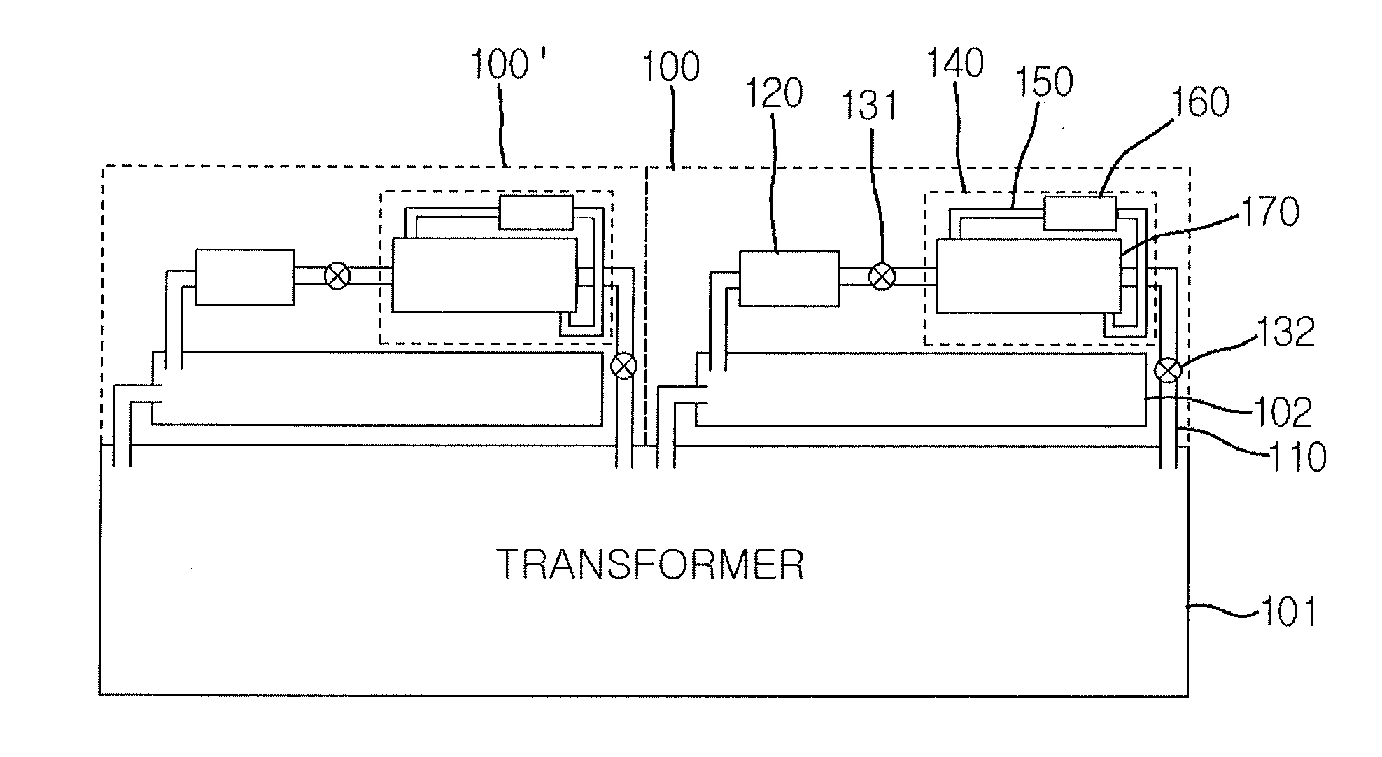
[0031]FIG. 1 is a conceptual diagram of a cooling system for a transformer to which heat exchange type cooling apparatuses 100 and 100′ for a transformer according to an exemplary embodiment of the present disclosure are applied.

[0032]As shown in FIG. 1, the heat exchange type cooling apparatuses 100 and 100′ for a transformer according to the exemplary embodiment of the present disclosure are configured so that an insulating oil filled in a transformer 101 may dissipate Joule heat generated by coils in the transformer 101 to the outside while being circulated. To this end, one side of the transformer 101 is provided with a tank 102 for supplying the insulating oil, which is cooled while being circulated by various pumps, or the like, to be described below and then returns into...


PUM

PropertyMeasurementUnit
boiling pointaaaaaaaaaa
thicknessaaaaaaaaaa
widthaaaaaaaaaa

Abstract

Disclosed herein is a heat exchange type cooling apparatus for a transformer, including: an insulating oil circulation pipe configured in a closed circuit form so that an insulating oil filled in the transformer is discharged to the outside and then returns again to the transformer; an insulating oil pump configured to transfer the insulating oil; and an insulating oil cooling system configured to cool the insulating oil, wherein the insulating oil cooling system includes: a liquid refrigerant maintained in a liquid state during the entire circulation cycle; a refrigerant circulation pipe configured to circulate the liquid refrigerant; a refrigerant pump configured to transfer the liquid refrigerant; and a heat exchanging part configured to heat-exchange the liquid refrigerant and the insulating oil with each other to cool the insulating oil.

Description

CROSS REFERENCE TO RELATED APPLICATION[0001]The present disclosure relates to subject matter contained in priority Korean Applications No. 10-2013-0005018, filed on Jan. 16, 2013, the entire contents of which are hereby incorporated by references in their entirety.BACKGROUND[0002]1. Field[0003]The present disclosure relates to a heat exchange type cooling apparatus for a transformer capable of having a light weight and exhibiting a low energy and high efficiency cooling performance.[0004]2. Description of the Related Art[0005]As a capacity of a transformer increases, a heat generation amount increases and a temperature rise becomes large, such that a problem occurs in a voltage transformation efficiency. Therefore, the transformer is filled with a transformer oil so as to prevent a temperature rise due to Joule heat flowing in a coil and is operated at a predetermined temperature by cooling the transformer oil. The transformer oil, which is an insulating oil obtained by fractionaliz...

Claims


Application Information

Patent Timeline
Patent Type & Authority Applications(United States)
IPC IPC(8): H01F27/00
CPCH01F27/008H01F27/12H01F27/16F28D15/00
Inventor KIM, GAP-DONG
Owner KIM GAP DONG
Why Eureka
Try Eureka